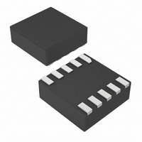
MAX4960ELB+T Maxim Integrated Products, MAX4960ELB+T Datasheet - Page 5

MAX4960ELB+T
Manufacturer Part Number
MAX4960ELB+T
Description
IC CTLR HI VOLTAGE OVP 10-UDFN
Manufacturer
Maxim Integrated Products
Datasheet
1.MAX4959ELBT.pdf
(17 pages)
Specifications of MAX4960ELB+T
Applications
*
Mounting Type
Surface Mount
Package / Case
10-µDFN
Lead Free Status / RoHS Status
Lead free / RoHS Compliant
The MAX4959/MAX4960 provide up to +28V overvoltage
protection for low-voltage systems. When the input volt-
age exceeds the overvoltage trip level, the MAX4959/
MAX4960 turn off an external pFET to prevent damage
to the protected components.
The MAX4959/MAX4960 feature a control bit (CB) pin
that controls an external battery-switchover function that
switches in the battery when the adapter is unconnect-
ed. The host system detects when the battery switchover
must take place and pulls CB high to turn on P2. The
load current is not interrupted during battery switchover
as the body diode of P2 conducts until the CB line is dri-
ven high (see the MAX4959 Typical Operating Circuit 1 ,
Figure 4).
An additional safety feature latches off pFET P1 when a
low-power adapter is plugged in. This protects the sys-
tem from seeing repeated adapter insertions and
removals when an incorrect low-power adapter is
plugged in that cannot provide sufficient current.
MAX4959
2, 9
10
—
1
3
4
5
6
7
8
PIN
High-Voltage OVP with Battery Switchover
MAX4960
10
1
9
2
3
4
5
6
7
8
_______________________________________________________________________________________
Detailed Description
SOURCE1
GATE1
GATE2
NAME
GND
N.C.
UVS
OVS
V
CB
IN
DD
pFET Gate Drive Output Open Drain. GATE1 is actively driven low, except during fault
(OVP or UVP) condition (the external pFET is turned off). When V
GATE1 is driven low (the external pFET P1 is turned on).
No Connection. Not internally connected. (Connect to ground or leave unconnected.)
pFET Source Output. An internal resistor is connected between SOURCE1 and GATE1.
Voltage Input. IN is both the power-supply input and the overvoltage/undervoltage
sense input. Bypass IN to GND with a 1µF ceramic capacitor to get a ±15kV protected
input. A minimum 0.1µF ceramic capacitor is required for proper operation.
Undervoltage Threshold Set Input. Connect UVS to an external resistive divider from IN to
GND to set the undervoltage lockout threshold. (See Typical Operating Circuits.)
Overvoltage Threshold Set Input. Connect OVS to an external resistive divider from
IN to GND to set the overvoltage lockout threshold. (See Typical Operating Circuits.)
Inter nal P ow er - S up p l y Outp ut. Byp ass V
V
Battery Switchover Control Input. When CB is high, GATE1 is high (P1 is off), and GATE2
is low (P2 is on). When CB is low, GATE1 is controlled by internal logic and GATE2 is
high (P2 is off). GATE1 is controlled by CB only if V
Ground
pFET Gate Drive Output, Open Drain. When CB is high, GATE2 is low (P2 is on).
When CB is low, GATE2 is high impedance (P2 is off).
DD
p ow er s the i nter nal p ow er - on r eset ci r cui ts. ( S ee the V
The MAX4959/MAX4960 have an adjustable undervolt-
age lockout threshold ranging from +5V to +28V. When
V
ing time, t
does not exist at the end of t
V
time, the device turns P1 off and P1 does not turn on
again until V
The MAX4959/MAX4960 have an adjustable overvolt-
age lockout threshold ranging from +6V to +28V. When
V
immediately. When V
again after the debounce time has elapsed.
If an adapter with a voltage higher than V
plugged in, the MAX4959/MAX4960 is in an OVP condi-
tion, so P1 is kept off or immediately turned off. There is
IN
IN
IN
is less than the V
is greater than the V
is less than V
BLANK
DD
FUNCTION
IN
to G N D w i th a 0.1µF m i ni m um cap aci tor .
< 0.75V. See Figure 1.
, to see if the fault still exists. If the fault
Undervoltage Lockout (UVLO)
High-Voltage Adapter (V
Overvoltage Lockout (OVLO)
UVLO
UVLO
UVLO
IN
drops below V
OVLO
for longer than the blanking
< V
D D
, the device waits for a blank-
IN
C ap aci tor S el ecti on secti on.)
BLANK
, the device turns P1 off
Pin Description
< V
UVLO
Device Operation
OVLO
, P1 remains on. If
< V
OVLO,
.
IN
< V
IN
P1 turns on
OVLO
> V
OVLO
OVLO
,
is
5
)


