NBSG16BAR2 ON Semiconductor, NBSG16BAR2 Datasheet - Page 2
NBSG16BAR2
Manufacturer Part Number
NBSG16BAR2
Description
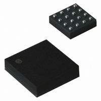
IC RCVR/DRVR RSECL SIGE 16FCBGA
Manufacturer
ON Semiconductor
Type
Transceiverr
Datasheet
1.NBSG16MNR2G.pdf
(12 pages)
Specifications of NBSG16BAR2
Applications
Instrumentation
Mounting Type
Surface Mount
Package / Case
16-FCBGA
Logic Family
NBSG
Logic Type
Differential Receiver and Driver
Supply Voltage (max)
- 3.465 V, 3.465 V
Supply Voltage (min)
- 2.375 V, 2.375 V
Maximum Operating Temperature
+ 85 C
Mounting Style
SMD/SMT
Data Rate
12000 Mbps
Minimum Operating Temperature
- 40 C
Number Of Lines (input / Output)
/ /
Supply Current
29 mA
Lead Free Status / RoHS Status
Contains lead / RoHS non-compliant
Other names
NBSG16BAR2OSTR
Available stocks
Company
Part Number
Manufacturer
Quantity
Price


Table 1. PIN DESCRIPTION
1. The NC pins are electrically connected to the die and MUST be left open.
2. All V
3. In the differential configuration when the input termination pins (VTD, VTD) are connected to a common termination voltage, and if no signal
A1,D1,A4,
B3,C3
A2,A3
BGA
bottom (see case drawing) must be attached to a heat−sinking conduit.
is applied then the device will be susceptible to self−oscillation.
N/A
C2
C1
D4
C4
D3
D2
B1
B2
B4
C
D
CC
A
B
Figure 1. BGA−16 Pinout (Top View)
Pin
and V
5,8,13,16
V
V
D
D
EE
EE
QFN
1
9,12
EE
6,7
10
14
15
11
1
2
3
4
−
pins must be externally connected to Power Supply to guarantee proper operation. The thermally exposed pad on package
VTD
VTD
V
NC
2
BB
Name
VTD
VTD
V
V
V
V
NC
EP
Q
Q
D
D
MM
CC
EE
BB
V
V
V
NC
MM
CC
CC
3
LVCMOS, LVDS,
LVCMOS, LVDS,
RSECL Output
RSECL Output
LVTTL Input
LVTTL Input
ECL, CML,
ECL, CML,
V
V
4
Q
Q
I/O
EE
EE
−
−
−
−
−
−
−
−
Internal 50 W Termination Pin. See Table 2.
Inverted Differential Input. Internal 75 kW to V
Noninverted differential input. Internal 75 kW to V
Internal 50 W Termination Pin. See Table 2.
Negative Supply Voltage
No Connect
Positive Supply Voltage
Noninverted Differential Output. Typically Terminated with 50 W to
V
Inverted Differential Output. Typically Terminated with 50 W to V
LVCMOS Reference Voltage Output. (V
ECL Reference Voltage Output
The Exposed Pad (EP) and the QFN−16 package bottom is thermally connected
to the die for improved heat transfer out of package. The exposed pad must be
attached to a heat−sinking conduit. The pad is not electrically connected to the
die but may be electrically and thermally connected to V
http://onsemi.com
TT
= V
CC
− 2 V
2
VTD
VTD
D
D
Figure 2. QFN−16 Pinout (Top View)
1
2
3
4
V
V
16
EE
EE
5
Description
V
15
NC
NBSG16
BB
6
CC
V
14
NC
7
MM
− V
EE
EE
V
V
13
and 36.5 kW to V
8
)/2
EE
EE
EE
EE
12
11
10
9
on the PC board.
V
Q
Q
V
Exposed Pad (EP)
CC
CC
TT
CC
= V
.
CC
− 2 V
Related parts for NBSG16BAR2
Image
Part Number
Description
Manufacturer
Datasheet
Request
R

Part Number:
Description:
Buffers & Line Drivers 2.5V/3.3V Multilevel
Manufacturer:
ON Semiconductor

Part Number:
Description:
ON Semiconductor [VOLTAGE REGULATOR]
Manufacturer:
ON Semiconductor
Datasheet:
Part Number:
Description:
357-036-542-201 CARDEDGE 36POS DL .156 BLK LOPRO
Manufacturer:
ON Semiconductor
Datasheet:
Part Number:
Description:
357-036-542-201 CARDEDGE 36POS DL .156 BLK LOPRO
Manufacturer:
ON Semiconductor
Datasheet:
Part Number:
Description:
357-036-542-201 CARDEDGE 36POS DL .156 BLK LOPRO
Manufacturer:
ON Semiconductor
Datasheet:
Part Number:
Description:
357-036-542-201 CARDEDGE 36POS DL .156 BLK LOPRO
Manufacturer:
ON Semiconductor
Datasheet:
Part Number:
Description:
357-036-542-201 CARDEDGE 36POS DL .156 BLK LOPRO
Manufacturer:
ON Semiconductor
Datasheet:
Part Number:
Description:
357-036-542-201 CARDEDGE 36POS DL .156 BLK LOPRO
Manufacturer:
ON Semiconductor
Datasheet:
Part Number:
Description:
357-036-542-201 CARDEDGE 36POS DL .156 BLK LOPRO
Manufacturer:
ON Semiconductor
Datasheet:
Part Number:
Description:
357-036-542-201 CARDEDGE 36POS DL .156 BLK LOPRO
Manufacturer:
ON Semiconductor
Datasheet:
Part Number:
Description:
357-036-542-201 CARDEDGE 36POS DL .156 BLK LOPRO
Manufacturer:
ON Semiconductor
Datasheet:
Part Number:
Description:
357-036-542-201 CARDEDGE 36POS DL .156 BLK LOPRO
Manufacturer:
ON Semiconductor
Datasheet:
Part Number:
Description:
Manufacturer:
ON Semiconductor
Datasheet: