6N140A Avago Technologies US Inc., 6N140A Datasheet - Page 8
6N140A
Manufacturer Part Number
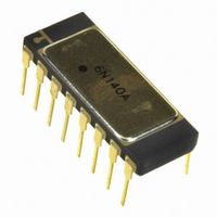
6N140A
Description
OPTOCOUPLER 4CH SEALED 16-DIP
Manufacturer
Avago Technologies US Inc.
Datasheet
1.6N139-500E.pdf
(12 pages)
Specifications of 6N140A
Mounting Type
Through Hole
Voltage - Isolation
1500VDC
Number Of Channels
4, Unidirectional
Current - Output / Channel
40mA
Data Rate
100KBd
Propagation Delay High - Low @ If
30µs @ 500µA
Current - Dc Forward (if)
10mA
Input Type
DC
Output Type
Open Collector
Package / Case
16-DIP (0.300", 7.62mm)
No. Of Channels
4
Optocoupler Output Type
Photodarlington
Input Current
5mA
Output Voltage
18V
Opto Case Style
DIP
No. Of Pins
16
Body Material
Gold Plated
Ctr Min
300%
Data Rate Max
100Kbps
Rohs Compliant
Yes
Lead Free Status / RoHS Status
Lead free / RoHS Compliant
Other names
516-1834-5
6N140A
6N140A
Available stocks
Company
Part Number
Manufacturer
Quantity
Price

Part Number:
6N140A
Manufacturer:
AVAGO/安华高
Quantity:
20 000
Company:
Part Number:
6N140A-883B
Manufacturer:
HP
Quantity:
27
Part Number:
6N140A/883
Manufacturer:
AVAGO/安华高
Quantity:
20 000
Part Number:
6N140A/883B
Manufacturer:
AVAGO/安华高
Quantity:
20 000


Electrical Characteristics (cont),
*
** All typical values are at V
Typical Characteristics,
8
Parameter
Propagation Delay
Time to Logic Low
at Output
Propagation Delay
Time to Logic High
at Output
Common Mode
Transient
Immunity at Low
Output Level
Common Mode
Transient
Immunity at High
Output Level
Parameter
Input Capacitance
Input Diode Temperature
Coefficient
Resistance (Input-Output)
Capacitance (Input-Output)
Dual and Quad Channel Product Only
Input-Input Leakage Current
Resistance (Input-Input)
Capacitance (Input-Input)
For JEDEC registered parts.
Symbol
t
t
t
t
t
t
|CM
|CM
PHL
PHL
PHL
PLH
PLH
PLH
T
CC
A
*
*
*
*
L
H
|
= 25°C, V
|
= 5 V, T
T
A
A
Test Conditions
I
V
I
V
I
V
I
V
I
V
I
VCC =5 V
V
R
|V
|V
VCC =5 V, I
R
|V
|V
= 25°C.
F
F
F
F
F
F
= -55°C to +125°C, unless otherwise specified
CC
CC
CC
CC
CC
CC
L
L
CC
Sym.
C
ΔV
R
C
I
R
C
= 0.5 mA, R
= 1.6 mA, R
=5 mA, R
= 0.5 mA, R
= 1.6 mA, R
=5 mA, R
CM
CM
CM
CM
I-I
=1.5 kΩ
=1.5 kΩ
I-O
I-I
IN
I-O
I-I
=5 V
=5 V
=5 V
=5 V
=5 V
=5 V, I
= 5 V
F
|= 25 V
|= 50 V
|= 25 V
|= 50 V
/ΔT
A
F
F
L
L
P-P [17]
P-P [16]
P-P
P-P [16]
= 1.6 mA
=0 mA
= 680 Ω,
= 680 Ω,
L
L
L
L
[17]
= 4.7 kΩ,
= 1.5 kΩ,
= 4.7 kΩ,
= 1.5 kΩ,
Typ.
60
-1.8
10
2.0
0.5
10
1.0
12
12
Group A
Subgroup
9, 10, 11
9, 10, 11
9
10, 11
9, 10, 11
9, 10, 11
9, 10, 11
9
10, 11
9, 10, 11
9, 10, 11
9, 10, 11
Units
pF
mV/°C
Ω
pF
nA
Ω
pF
[13]
Min.
500
500
Typ.**
30
5
2
17
14
8
1000
1000
Test Conditions
V
I
V
f = 1 MHz
Relative Humidity = ≤65%,
V
V
f = 1 MHz
F
F
I-O
I-I
I-I
= 1.6 mA
Limits
=0 V, f = 1 MHz
= 500 V, t = 5 s
= 500 V
= 500 V
Max.
100
30
5
10
10
60
50
20
30
30
Units
µs
µs
V/µs
V/µs
Fig.
5, 6,
7, 8
5, 6,
7, 8
9
9
Note
4
4
4, 8
4, 8
9
9
9
Note
4
4, 16
4, 17
4, 16
4
4, 16
4, 17
4, 16
11, 14
11, 14
4, 10
4, 10
Related parts for 6N140A
Image
Part Number
Description
Manufacturer
Datasheet
Request
R

Part Number:
Description:
OPTOCOUPLER GATE DRV 2A 16-SOIC
Manufacturer:
Avago Technologies US Inc.
Datasheet:
Part Number:
Description:
OPTOCOUPLER 2CH 2.5A 16-SOIC
Manufacturer:
Avago Technologies US Inc.
Datasheet:

Part Number:
Description:
OPTOCOUPLER GATE DRV 0.4A 16SOIC
Manufacturer:
Avago Technologies US Inc.
Datasheet:

Part Number:
Description:
OPTOCOUPLER 2.0A 250KHZ 8-DIP
Manufacturer:
Avago Technologies US Inc.
Datasheet:

Part Number:
Description:
OPTOCOUPLER 2.0A 250KHZ GW 8-SMD
Manufacturer:
Avago Technologies US Inc.
Datasheet:

Part Number:
Description:
OPTOCOUPLER 2CH 15MBD 3.3V 8SOIC
Manufacturer:
Avago Technologies US Inc.
Datasheet:
Part Number:
Description:
OPTOCOUPLER DARL-OUT 8-DIP
Manufacturer:
Avago Technologies US Inc.
Datasheet:
Part Number:
Description:
OPTOCOUPLER IGBT DRIVE 0.4A 8DIP
Manufacturer:
Avago Technologies US Inc.
Datasheet:
Part Number:
Description:
OPTOCOUPLER DARL-OUT 8-DIP
Manufacturer:
Avago Technologies US Inc.
Datasheet:

Part Number:
Description:
OPTOCOUPLER 1CH 1MBS 8-SMD GW
Manufacturer:
Avago Technologies US Inc.
Datasheet:
Part Number:
Description:
OPTOCOUPLER GATE DRIVER 8-DIP
Manufacturer:
Avago Technologies US Inc.
Datasheet:

Part Number:
Description:
OPTOCOUPLER GATE DRIVER 8-SMD
Manufacturer:
Avago Technologies US Inc.
Datasheet:

Part Number:
Description:
OPTOCOUPLER PHOTOTRANS 4-SMD
Manufacturer:
Avago Technologies US Inc.
Datasheet:

Part Number:
Description:
OPTOCOUPLER W/BASE 6-DIP
Manufacturer:
Avago Technologies US Inc.
Datasheet:

Part Number:
Description:
ISOLAT 5KVRMS 4CH TRANS 16SMD GW
Manufacturer:
Avago Technologies US Inc.
Datasheet: