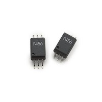
ACPL-P454-560E Avago Technologies US Inc., ACPL-P454-560E Datasheet - Page 9

ACPL-P454-560E
Manufacturer Part Number
ACPL-P454-560E
Description
OPTOCOUPLER 1MBD VDE 6-SOIC
Manufacturer
Avago Technologies US Inc.
Specifications of ACPL-P454-560E
Input Type
DC
Package / Case
SO-6
Voltage - Isolation
3750Vrms
Number Of Channels
1, Unidirectional
Current - Output / Channel
8mA
Propagation Delay High - Low @ If
200ns @ 16mA
Current - Dc Forward (if)
25mA
Output Type
Open Collector
Mounting Type
Surface Mount
Isolation Voltage
3750 Vrms
Output Device
Phototransistor
Configuration
1 Channel
Current Transfer Ratio
37 %
Maximum Forward Diode Voltage
1.7 V
Maximum Reverse Diode Voltage
5 V
Maximum Input Diode Current
25 mA
Maximum Power Dissipation
100 mW
Maximum Operating Temperature
+ 70 C
Minimum Operating Temperature
0 C
Lead Free Status / RoHS Status
Lead free / RoHS Compliant
Figure 8. Propagation Delay Time vs. Tempera-
ture.
Figure 11. Propagation Delay Time vs. Tempera-
ture.
Figure 14. Propagation Delay Time vs. Supply
Voltage.
For product information and a complete list of distributors, please go to our web site:
Avago, Avago Technologies, and the A logo are trademarks of Avago Technologies in the United States and other countries.
Data subject to change. Copyright © 2005-2010 Avago Technologies. All rights reserved. Obsoletes AV01-0253EN
AV02-1307EN - August 4, 2010
0.4
0.15
1.1
1.0
0.9
0.8
0.7
0.6
0.5
0.3
0.50
0.45
0.40
0.35
0.30
0.25
0.20
0.10
1.2
1.1
1.0
0.9
0.8
0.7
0.6
0.5
0.4
0.3
0.2
-60
-60
10
V
R
C
V
V
50% DUTY CYCLE
V
R
C
V
10% DUTY CYCLE
CC
-40 -20
L
THHL
THLH
L
CC
11 12 13 14 15 16 17 18 19
L
L
THHL
= 100 pF
-40 -20
= 20 k
= 1.9 k
= 15 pF
= 15.0 V
= 5.0 V
t
t
t
PHL
V
= 1.5 V
= 2.0 V
PLH
PHL
CC
= V
t
T
PHL
T
A
- SUPPLY VOLTAGE - V
A
THLH
0
- TEMPERATURE - ˚C
- TEMPERATURE - ˚C
0
20 40
20 40 60 80 100 120
= 1.5 V
I
I
F
F
T
R
C
V
V
50% DUTY CYCLE
I
I
I
I
F
F
F
F
A
L
L
THHL
THLH
= 10 mA
= 16 mA
= 25 ˚C
= 10 mA
= 16 mA
= 20 k
= 100 pF
= 10 mA
= 16 mA
60 80 100 120
= 1.5 V
= 2.0 V
t
PLH
t
PLH
20
Figure 9. Propagation Delay Time vs. Load Resis-
tance.
Figure 12. Propagation Delay Time vs. Load Re-
sistance.
1.8
1.6
1.4
1.2
1.0
0.8
0.6
0.4
0.2
0.0
1.4
1.2
1.0
0.8
0.6
0.4
0.2
0.0
0
0
V
T
C
V
10% DUTY CYCLE
V
T
C
V
V
50% DUTY CYCLE
A
A
CC
CC
THLH
THHL
L
THHL
L
2
5
= 25 ˚C
= 100 pF
= 25 ˚C
= 15 pF
= 15.0 V
= 5.0 V
10 15 20
4
= 1.5 V
= 2.0 V
= V
R
L
6
R
- LOAD RESISTANCE - k
THLH
L
t
- LOAD RESISTANCE - k
PHL
www.avagotech.com
8 10 12 14 16 18
= 1.5 V
25 30 35 40 45
I
I
I
I
F
F
F
F
t
PHL
= 10 mA
= 16 mA
= 10 mA
= 16 mA
t
t
PLH
PLH
50
20
Figure 10. Propagation Delay Time vs. Load
Resistance.
Figure 13. Propagation Delay Time vs. Load
Capacitance.
3.5
3.0
2.5
2.0
1.5
1.0
0.5
0.0
2.6
2.4
2.2
2.0
1.8
1.6
1.4
1.2
1.0
0.8
0.6
0.4
0.2
0.0
0
0
V
T
R
V
V
50% DUTY CYCLE
V
T
C
V
V
50% DUTY CYCLE
A
A
CC
CC
THLH
L
THHL
THLH
L
THHL
2
= 25 ˚C
= 20 k
= 25 ˚C
= 100 pF
= 15.0 V
= 5.0 V
200
4
= 1.5 V
= 1.5 V
= 2.0 V
= 2.0 V
C
L
R
- LOAD CAPACITANCE - pF
6
L
t
- LOAD RESISTANCE - k
PHL
400
8
10 12 14 16 18
I
I
I
I
F
F
F
F
600
= 10 mA
= 16 mA
= 10 mA
= 16 mA
t
t
t
800
PHL
PLH
PLH
1000
20


