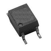
HCPL-M601-560E Avago Technologies US Inc., HCPL-M601-560E Datasheet - Page 6

HCPL-M601-560E
Manufacturer Part Number
HCPL-M601-560E
Description
OPTOCOUPLER 10MBD LOGIC VDE SO-5
Manufacturer
Avago Technologies US Inc.
Datasheet
1.HCPL-M611-000E.pdf
(11 pages)
Specifications of HCPL-M601-560E
Voltage - Isolation
3750Vrms
Number Of Channels
1, Unidirectional
Current - Output / Channel
50mA
Data Rate
10MBd
Propagation Delay High - Low @ If
25ns @ 7.5mA
Current - Dc Forward (if)
20mA
Input Type
DC
Output Type
Open Collector
Mounting Type
Surface Mount
Package / Case
SO-5 (MO-155)
No. Of Channels
1
Optocoupler Output Type
Logic Gate
Input Current
15mA
Output Voltage
5.5V
Opto Case Style
SOIC
No. Of Pins
5
Peak Reflow Compatible (260 C)
Yes
Isolation Voltage
3.75kV
Number Of Elements
1
Baud Rate
10Mbps
Forward Voltage
1.75V
Forward Current
20mA
Output Current
50mA
Package Type
SOIC
Operating Temp Range
-40C to 85C
Power Dissipation
85mW
Propagation Delay Time
75ns
Pin Count
5
Mounting
Surface Mount
Reverse Breakdown Voltage
5V
Operating Temperature Classification
Industrial
Lead Free Status / RoHS Status
Lead free / RoHS Compliant
Lead Free Status / RoHS Status
Lead free / RoHS Compliant, Lead free / RoHS Compliant
Insulation Related Specifications
Electrical Specifications
Over recommended temperature (T
*All typicals at T
6
Parameter
Min. External Air Gap
(Clearance)
Min. External Tracking Path
(Creepage)
Min. Internal Plastic Gap
(Clearance)
Tracking Resistance
Isolation Group (per DIN VDE 0109)
Parameter
Input Threshold
Current
High Level Output
Current
Low Level Output
Voltage
High Level Supply
Current
Low Level Supply
Current
Input Forward
Voltage
Input Reverse
Breakdown Voltage
Input Capacitance
Input Diode
Temperature
Coefficient
Input-Output
Insulation
Resistance
(Input-Output)
Capacitance
(Input-Output)
A
= 25°C, V
CC
= 5 V.
∆V
Symbol
I
I
BV
V
R
C
V
C
I
I
CCH
F
CCL
V
OH
TH
ISO
OL
/∆T
I-O
I-O
IN
F
R
A
A
= -40°C to 85°C) unless otherwise specified. (See note 1.)
3750
Min.
1.4
1.3
5
Typ.*
10
Symbol
-1.6
5.5
0.4
1.5
0.6
L(IO1)
L(IO2)
60
2
4
6
CTI
12
Max.
10.5
1.75
1.85
100
0.6
7.5
5
Value
0.08
175
IIIa
≥5
≥5
mV/°C
Units
V
mA
mA
mA
μA
pF
pF
RMS
Ω
V
V
Units
mm
mm
mm
V
Test Conditions
V
V
V
I
V
I
V
V
T
I
I
V
RH ≤ 50%, t = 1 min.
V
f = 1 MHz
F
OL
F
R
I
A
CC
CC
F
F
I-O
O
CC
CC
CC
= 250 μA
= 10 mA
= 10 μA
= 25°C, I
= 0V, f = 1 MHz
= 10 mA
= 0.6 V
(Sinking) = 13 mA
= 5.5 V, I
= 5.5 V, I
= 5.5 V, V
= 5.5 V, I
= 5.5 V, I
= 500 V
Conditions
Measured from input terminals
to output terminals
Measured from input terminals
to output terminals
Through insulation distance
conductor to conductor
DIN IEC 112/VDE 0303 Part 1
Material Group DIN VDE 0109
F
=10 mA
O
F
F
F
O
= 0 mA,
≥13 mA,
= 5 mA,
= 10 mA,
= 5.5 V
5, 13
2, 4,
Fig.
13
12
1
3
Note
3, 4
3
3


