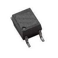
HCPL-M601 Avago Technologies US Inc., HCPL-M601 Datasheet - Page 3

HCPL-M601
Manufacturer Part Number
HCPL-M601
Description
OPTOCOUPLER 10MBD LOGIC SO-5
Manufacturer
Avago Technologies US Inc.
Datasheet
1.HCPL-M611-000E.pdf
(11 pages)
Specifications of HCPL-M601
Package / Case
5-SOP
Voltage - Isolation
3750Vrms
Number Of Channels
1, Unidirectional
Current - Output / Channel
50mA
Data Rate
10MBd
Propagation Delay High - Low @ If
25ns @ 7.5mA
Current - Dc Forward (if)
20mA
Input Type
DC
Output Type
Open Collector
Mounting Type
Surface Mount
Isolation Voltage
3750 Vrms
Maximum Continuous Output Current
50 mA
Maximum Fall Time
10 ns
Maximum Forward Diode Current
20 mA
Maximum Rise Time
24 ns
Minimum Forward Diode Voltage
1.4 V
Output Device
Logic Gate Photo IC
Configuration
1 Channel
Maximum Baud Rate
10 MBps
Maximum Forward Diode Voltage
1.75 V
Maximum Reverse Diode Voltage
5 V
Maximum Power Dissipation
85 mW
Maximum Operating Temperature
+ 85 C
Minimum Operating Temperature
- 40 C
Lead Free Status / RoHS Status
Contains lead / RoHS non-compliant
Available stocks
Company
Part Number
Manufacturer
Quantity
Price
Company:
Part Number:
HCPL-M601
Manufacturer:
EVERLIGHT
Quantity:
34 680
Part Number:
HCPL-M601
Manufacturer:
AGILENT
Quantity:
20 000
Company:
Part Number:
HCPL-M601#000E
Manufacturer:
AVAGO
Quantity:
45 000
Company:
Part Number:
HCPL-M601#500
Manufacturer:
AGILENT
Quantity:
20 000
Company:
Part Number:
HCPL-M601#500E
Manufacturer:
AVAGO
Quantity:
45 000
Company:
Part Number:
HCPL-M601-500E
Manufacturer:
AVAGO
Quantity:
37 000
Part Number:
HCPL-M601-500E
Manufacturer:
AVAGO/安华高
Quantity:
20 000
Part Number:
HCPL-M601-500E/HCPLM601-500E
Manufacturer:
AVAGO/安华高
Quantity:
20 000
Outline Drawing (JEDEC MO-155)
Land Pattern Recommendation
Regulatory Information
The HCPL-M600, HCPL-M601 and HCPL-M611 are approved by the following organizations:
IEC/EN/DIN EN 60747-5-5 (Option 060 only)
for HCPL-M601 and HCPL-M611
3
(0.173 ± 0.004)
(0.098 ± 0.004)
DIMENSIONS IN MILLIMETERS (INCHES)
* MAXIMUM MOLD FLASH ON EACH SIDE IS 0.15 mm (0.006)
NOTE: FLOATING LEAD PROTRUSION IS 0.15 mm (6 mils) MAX.
(0.10)
2.5
4.4 ± 0.1
2.5 ± 0.1
(0.080)
2.0
(0.050)
1.27
BSC
(0.142 ± 0.004)
MXXX
XXX
3.6 ± 0.1*
(0.17)
(0.325)
4.4
8.27
(0.016 ± 0.002)
(0.004 ± 0.004)
0.102 ± 0.102
(0.276 ± 0.008)
0.4 ± 0.05
7.0 ± 0.2
(0.028)
0.71
CATHODE
MIN.
ANODE
(0.05)
1.3
1
3
(0.025)
0.64
MAX. LEAD COPLANARITY
= 0.102 (0.004)
Schematic
UL
Approval under UL 1577, component recognition pro-
gram up to V
CSA
Approval under CSA Component Acceptance Notice #5,
File CA 88324.
+
1
–
3
USE OF A 0.1 μF BYPASS CAPACITOR
MUST BE CONNECTED BETWEEN PINS
6 AND 4 (SEE NOTE 1).
I
F
HCPL-M601/11 SHIELD
(0.0085 ± 0.0015)
6
4
5
0.216 ± 0.038
ISO
V
V
GND
CC
OUT
= 3750 V
7° MAX.
RMS
.
(POSITIVE LOGIC)
TRUTH TABLE
LED
OFF
ON
I
CC
I
O
OUTPUT
5
4
6
L
H
V
V
GND
CC
O


