ACPL-M43T Avago Technologies US Inc., ACPL-M43T Datasheet - Page 6
ACPL-M43T
Manufacturer Part Number
ACPL-M43T
Description
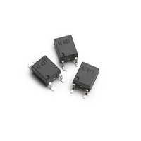
OPTOCOUPLER AUTO 1MBD 5-SOIC
Manufacturer
Avago Technologies US Inc.
Series
R²Coupler™r
Specifications of ACPL-M43T
Input Type
DC
Package / Case
6-SOIC (0.173", 4.40mm Width) 5 Leads
Voltage - Isolation
3750Vrms
Number Of Channels
1, Unidirectional
Current - Output / Channel
8mA
Data Rate
1MBd
Propagation Delay High - Low @ If
200ns @ 10mA
Current - Dc Forward (if)
20mA
Output Type
Open Collector
Mounting Type
Surface Mount
Isolation Voltage
3750 Vrms
Minimum Forward Diode Voltage
1.45 V
Output Device
Phototransistor
Configuration
1 Channel
Current Transfer Ratio
45 %
Maximum Baud Rate
1 MBps
Maximum Forward Diode Voltage
1.85 V
Maximum Reverse Diode Voltage
5 V
Maximum Input Diode Current
20 mA
Maximum Power Dissipation
100 mW
Maximum Operating Temperature
+ 125 C
Minimum Operating Temperature
- 40 C
Lead Free Status / RoHS Status
Contains lead / RoHS non-compliant
Available stocks
Company
Part Number
Manufacturer
Quantity
Price

Part Number:
ACPL-M43T
Manufacturer:
AVAGO/安华高
Quantity:
20 000
Part Number:
ACPL-M43T-000E
Manufacturer:
AVAGO/安华高
Quantity:
20 000


Switching Specifications (AC)
Over recommended operating (T
Package Characteristics
*The Input-Output Momentary Withstand Voltage is a dielectric voltage rating that should not be interpreted as an
input-output continuous voltage rating.
Notes:
1. Derate linearly above 85°C free-air temperature at a rate of 0.25 mA/°C.
2. Derate linearly above 85°C free-air temperature at a rate of 0.30 mA/°C.
3. Derate linearly above 85°C free-air temperature at a rate of 0.375 mW/°C.
4. Derate linearly above 85°C free-air temperature at a rate of 1.875 mW/°C.
5. CURRENT TRANSFER RATIO in percent is defined as the ratio of output collector current, I
6. Device considered a two terminal device: pins 1 and 3 shorted together, and pins 4, 5 and 6 shorted together.
7. In accordance with UL 1577, each optocoupler is proof tested by applying an insulation test voltage t 4800 V
8. Common transient immunity in a Logic High level is the maximum tolerable (positive) dV
9. The 1.9 k: load represents 1 TTL unit load of 1.6 mA and the 5.6 k: pull-up resistor.
10. The frequency at which the ac output voltage is 3 dB below its mid-frequency value.
11. Use of a 0.1 μF bypass capacitor connected between pins 4 and 6 is recommended.
12. Pulse Width Distortion (PWD) is defined as |t
13. The difference between t
6
Parameter
Propagation Delay
Time to Logic Low
at Output
Propagation Delay
Time to Logic High
at Output
Pulse Width
Distortion
Propagation Delay
Difference Between
Any 2 Parts
Common Mode
Transient Immunity
at Logic High Output
Common Mode
Transient Immunity
at Logic Low Output
Parameter
Input-Output Momentary
Withstand Voltage*
Input-Output Resistance
Input-Output Capacitance
to assure that the output will remain in a Logic High state (i.e., V
tolerable (negative) dV
(i.e., V
O
< 0.8 V).
CM
PLH
/dt on the falling edge of the common mode pulse signal, V
Symbol
T
T
PWD
t
|CM
|CM
PLH
PHL
PLH
and t
-t
H
L
|
|
PHL
PHL
Symbol
V
R
C
between any two parts under the same test condition.
A
ISO
I-O
I-O
= -40°C to 125°C), I
Min
0.08
0.06
0.15
0.03
0
0
0
0
15
15
PHL
- t
Typ
0.2
0.3
0.4
0.4
30
30
Min.
4000
PLH
| for any given device.
Max
0.8
1.0
0.8
1.0
0. 45
0.85
0.5
0.9
Typ.
10
0.6
14
F
O
> 2.0 V). Common mode transient immunity in a Logic Low level is the maximum
= 10mA, V
Units
μs
μs
μs
μs
μs
μs
μs
μs
kV/μs
kV/μs
Max.
T
T
T
T
A
A
A
A
CC
=25°C
=25°C
=25°C
=25°C
= 5.0 V unless otherwise specified.
Units
V
:
pF
RMS
CM
CM
Test Conditions
Pulse: f=10kHz, Duty cycle =50%,
I
C
Pulse: f=10kHz, Duty cycle =50%,
I
C
Pulse: f=10kHz, Duty cycle =50%,
I
C
Pulse: f=10kHz, Duty cycle =50%,
I
C
V
R
V
T
F
F
F
F
O
to assure that the output will remain in a Logic Low state
A
CM
L
CM
L
L
=10mA, V
L
=10mA, V
L
, to the forward LED input current, I
= 10mA, V
= 10mA, V
=15pF, V
=15pF, V
=1.9k:
=25°C, R
/dt on the rising edge of the common mode pulse, V
= 15pF V
= 15pF V
=1500Vp-p, I
=1500Vp-p, I
Test Conditions
RH d 50%, t = 1 min;
T
V
f = 1 MHz; V
A
I-O
= 25°C
= 500 Vdc
L
THHL
THHL
CC
CC
=1.9k:
THHL
THLH
CC
CC
=5.0V, R
=5.0V, R
= 5.0 V, R
= 5.0 V, R
=1.5V, V
=1.5V, V
=1.5V
=2.0V
F
F
I-O
=0mA, T
=10mA,
RMS
= 0 Vdc
L
L
=1.9k:,
=1.9k:,
for 1 second.
THLH
THLH
L
L
= 1.9k:
= 1.9k:
A
=25°C,
=2.0V
=2.0V
Fig.
F
, times 100.
Fig.
5,6,7,
8,9,
10,13
5,6,7,
8,9,
10,13
14
14
Note
6, 7
6
6
Note
9
9
12
13
8, 9
CM
,
Related parts for ACPL-M43T
Image
Part Number
Description
Manufacturer
Datasheet
Request
R

Part Number:
Description:
ISOLAT 5KVRMS 4CH TRANS 16SMD GW
Manufacturer:
Avago Technologies US Inc.
Datasheet:

Part Number:
Description:
OPTOCOUPLER 2.5A IGBT 8-DIP
Manufacturer:
Avago Technologies US Inc.
Datasheet:
Part Number:
Description:
OPTOCOUPLER IGBT 2.5A 16-SOIC
Manufacturer:
Avago Technologies US Inc.
Datasheet:

Part Number:
Description:
Dual Line Driver,LF
Manufacturer:
Avago Technologies US Inc.
Datasheet:
Part Number:
Description:
Amplifier-Output Optocoupler,2-CHANNEL,3.75kV ISOLATION,SO
Manufacturer:
Avago Technologies US Inc.
Datasheet:
Part Number:
Description:
Hermetic Optocoupler
Manufacturer:
Avago Technologies US Inc.
Datasheet:
Part Number:
Description:
Automotive 10MBd Coupler
Manufacturer:
Avago Technologies US Inc.
Datasheet:
Part Number:
Description:
Amplifier-Output Optocoupler,1-CHANNEL,DIP
Manufacturer:
Avago Technologies US Inc.
Datasheet:
Part Number:
Description:
ISOLATOR 5KVRMS 1CH GATE 8SOIC
Manufacturer:
Avago Technologies US Inc.
Datasheet:

Part Number:
Description:
OPTOCOUPLER PHOTOTRANS SO-4
Manufacturer:
Avago Technologies US Inc.
Datasheet:

Part Number:
Description:
ISOLATOR 3KVRMS 1CH TRANS SO-4
Manufacturer:
Avago Technologies US Inc.
Datasheet:
Part Number:
Description:
ISOLATOR 3KVRMS 1CH TRANS SO-4
Manufacturer:
Avago Technologies US Inc.
Datasheet:
Part Number:
Description:
ISOLATOR 3KVRMS 1CH TRANS SO-4
Manufacturer:
Avago Technologies US Inc.
Datasheet:
Part Number:
Description:
ISOLATOR 3KVRMS 1CH TRANS SO-4
Manufacturer:
Avago Technologies US Inc.
Datasheet:

Part Number:
Description:
ISOLATOR 3KVRMS 1CH TRANS SO-4
Manufacturer:
Avago Technologies US Inc.
Datasheet: