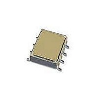
5962-0420501HXA Avago Technologies US Inc., 5962-0420501HXA Datasheet - Page 13

5962-0420501HXA
Manufacturer Part Number
5962-0420501HXA
Description
OPTOCOUPLER IGBT 0.5A GATE DVR
Manufacturer
Avago Technologies US Inc.
Datasheet
1.HCPL-5150.pdf
(16 pages)
Specifications of 5962-0420501HXA
Output Type
Gate Driver
Package / Case
8-SMD Gull Wing
Voltage - Isolation
1500VDC
Number Of Channels
1, Unidirectional
Current - Output / Channel
600mA
Propagation Delay High - Low @ If
300ns @ 10mA ~ 18mA
Current - Dc Forward (if)
25mA
Input Type
DC
Mounting Type
Surface Mount
Configuration
1 Channel
Maximum Propagation Delay Time
500 ns
Maximum Forward Diode Voltage
1.8 V
Minimum Forward Diode Voltage
1.2 V
Maximum Reverse Diode Voltage
5 V
Maximum Forward Diode Current
18 mA
Maximum Power Dissipation
295 mW
Maximum Operating Temperature
+ 125 C
Minimum Operating Temperature
- 55 C
Lead Free Status / RoHS Status
Contains lead / RoHS non-compliant
Figure 26. Typical Application Circuit with Negative IGBT Gate Drive
Figure 27. Energy Dissipated in the HCPL-5150 for Each
IGBT Switching Cycle
3
CONTROL
INPUT
P
I
V
Duty Cycle
P
I
V
V
E
f
F
CC
SW
F
CC
EE
E
O
7
6
5
4
3
2
1
0
Parameter
Parameter
(R
0
+5 V
74XXX
OPEN
COLLECTOR
g
, Q
g
)
20
Rg - GATE RESISTANCE - Ω
270
Ω
40
Description
LED Current
LED On Voltage
Maximum LED Duty Cycle
Description
Supply Current
Positive Supply Voltage
Negative Supply Voltage
Energy Dissipation in the HCPL-550 for each IGBT
Switching Cycle (See Figure 7)
Switching Frequency
60
Qg = 100 nC
Qg = 250 nC
Qg = 500 nC
V
V
CC
EE
1
2
3
4
= 19 V
= -9 V
80
100
Figure 28. Optocoupler Input to Output Capacitance
Model for Unshielded Optocouplers
1
2
3
4
C
C
LEDP
LEDN
8
7
6
5
0.1 µF
+
_
+
_
LED Drive Circuit Considerations for Ultra High CMR Perfor-
mance.
Without a detector shield, the dominant cause of opto-
coupler CMR failure is capacitive coupling from the input
side of the optocoupler, through the package, to the
detector IC as shown in Figure 28.
The HCPL-5150 improves CMR performance by using a
detector IC with an optically transparent Faraday shield,
which diverts the capacitively coupled current away from
the sensitive IC circuitry. However, this shield does not
eliminate the capacitive coupling between the LED and
optocoupler pins 5-8 as shown in Figure 29. This capaci-
tive coupling causes perturbations in the LED current
during common mode transients and becomes the major
source of CMR failures for a shielded optocoupler. The
main design objective of a high CMR LED drive circuit
becomes keeping the LED in the proper state (on or off )
during common mode transients. For example, the rec-
ommended application circuit, (Figure 25) can achieve
10 kV/ms CMR while minimizing component complex-
ity. Techniques to keep the LED in the proper state are
discussed in the next two sections.
V
V
CC
EE
Rg
= 15 V
= -5 V
8
7
6
5
Q1
Q2
Figure 29. Optocoupler Input to Output Capacitance
Model for Shielded Optocouplers
1
2
3
4
C
C
LEDP
LEDN
SHIELD
C
LEDO1
3-PHASE
+ HVDC
- HVDC
AC
C
LEDO2
8
7
6
5


