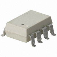
HCNR201-300E Avago Technologies US Inc., HCNR201-300E Datasheet

HCNR201-300E
Specifications of HCNR201-300E
Available stocks
Related parts for HCNR201-300E
HCNR201-300E Summary of contents
Page 1
... HCNR200 and HCNR201 High-Linearity Analog Optocouplers Data Sheet Lead (Pb) Free RoHS 6 fully compliant RoHS 6 fully compliant options available; -xxxE denotes a lead-free product Description The HCNR200/201 high-linearity analog optocoupler consists of a high-performance AlGaAs LED that illumi- nates two closely matched photodiodes. The input pho- todiode can be used to monitor, and therefore stabilize, the light output of the LED ...
Page 2
... IORM peak Example 2: HCNR201 to order product of 8-Pin Widebody DIP package in Tube packaging with UL 5000 Vrms for 1 minute rating and non RoHS compliant. Option datasheets are available. Contact your Avago sales representative or authorized distributor for information. Remarks: The notation ‘#XXX’ is used for existing products, while (new) products launched since July 15, 2001 and RoHS compliant will use ‘ ...
Page 3
Package Outline Drawings 11.30 (0.445) MAX HCNR200Z YYWW PIN ONE 1.70 (0.067) 1.80 (0.071) Figure OPTION 9.00 CODE* (0.354) TYP. DATE CODE 11.00 (0.433) MAX. 4 1.50 (0.059) MAX. 1 ...
Page 4
Gull Wing Surface Mount Option #300 11.15 ± 0.15 (0.442 ± 0.006 1.78 ± 0.15 (0.070 ± 0.006) 2.54 (0.100) BSC DIMENSIONS IN MILLIMETERS (INCHES). LEAD COPLANARITY = 0.10 mm (0.004 INCHES). NOTE: FLOATING ...
Page 5
Solder Refl ow Temperature Profi le 300 PREHEATING RATE 3 ° °C/–0.5 °C/SEC. REFLOW HEATING RATE 2.5 °C ± 0.5 °C/SEC. 200 160 °C 150 °C 140 °C 3 ° °C/–0.5 °C 100 ROOM TEMPERATURE 0 ...
Page 6
Insulation and Safety Related Specifi cations Parameter Min. External Clearance (External Air Gap) Min. External Creepage (External Tracking Path) Min. Internal Clearance (Internal Plastic Gap) Min. Internal Creepage (Internal Tracking Path) Comparative Tracking Index Isolation Group Option 300 – surface ...
Page 7
Absolute Maximum Ratings Storage Temperature ..............................................................................................-55°C to +125°C Operating Temperature (T ) ................................................................................. -55°C to +100°C A Junction Temperature (T ) ......................................................................................................... 125°C J Refl ow Temperature Profi le ..............................................See Package Outline Drawings Section Lead Solder Temperature ............................................................................................260°C for 10s ...
Page 8
... A Coeffi cient of Transfer Gain DC NonLinearity NL HCNR200 BF (Best Fit) HCNR201 HCNR201 DC Nonlinearity NL EF (Ends Fit) Input Photo- K HCNR200 1 diode Current Transfer Ratio HCNR201 ( PD1 F Temperature ΔK /Δ Coeffi cient Photodiode I LK Leakage Current Photodiode BV RPD Reverse Break- down Voltage Photodiode ...
Page 9
AC Electrical Specifi cations T = 25°C unless otherwise specifi ed. A Parameter LED Bandwidth Application Circuit Bandwidth: High Speed High Precision Application Circuit: IMRR High Speed Package Characteristics T = 25°C unless otherwise specifi ed. A Parameter Symbol Input-Output ...
Page 10
NORM K3 MEAN = NORM K3 MEAN ± 2 • STD DEV 1.04 1.02 1.00 0.98 0.96 NORMALIZED TO BEST-FIT 25° < V < 0.94 0.0 10.0 20.0 ...
Page 11
P OUTPUT POWER – 900 I INPUT CURRENT – 800 700 600 500 400 300 200 100 100 125 150 T – CASE TEMPERATURE – °C S Figure 11. Thermal ...
Page 12
V CC1 V IOS1 CC1 SINGLE OPTOCOUPLER DUAL OPTOCOUPLER Figure 14. Bipolar circuit topologies PD1 + LED ...
Page 13
CC1 LED 2N3904 2N3906 R4 10 PD1 Figure 16. High-speed low-cost analog isolator. V +15 V CC1 C3 0.1µ 200 K P INPUT BNC ...
Page 14
D1 R1 220 K V OC1 IN PD1 +15 V CC1 V = -15 V EE1 Figure 19. Magnitude/sign isolation amplifi er. Figure 20. SPICE model listing ...
Page 15
R1 10 kΩ HCNR200 PD1 R2 10 kΩ -ILOOP R3 25 Ω Design Equations: VOUT / ILOOP = K3 ( Constant = 1 Note: The two OP-AMPS shown ...
Page 16
Theory of Operation Figure 1 illustrates how the HCNR200/201 high-linearity opto coup ler is confi gured. The basic optocoupler con- sists of an LED and two photodiodes. The LED and one of the photodiodes (PD1 the input leadframe ...
Page 17
Circuit Design Flexibility Circuit design with the HCNR200/201 is very fl exible because the LED and both photodiodes are acces sible to the designer. This allows the designer to make perf- ormance trade-off s that would otherwise be diffi cult ...
Page 18
The preceding circuits were pre sented to illustrate the fl exibility in designing analog isolation circuits using the HCNR200/201. The next section presents several com- plete schematics to illustrate practical applications of the HCNR200/201. Example Application Circuits The circuit shown ...
Page 19
The fi nal circuit shown in Figure 19 isolates a bipolar analog signal using only one optocoupler and generates two output signals: an analog signal proportional to the magnitude of the input signal and a digital signal cor- responding to ...


