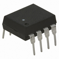
HCNR201 Avago Technologies US Inc., HCNR201 Datasheet - Page 15

HCNR201
Manufacturer Part Number
HCNR201
Description
OPTOCOUPLR ANLG HI-LIN 8DIP WIDE
Manufacturer
Avago Technologies US Inc.
Datasheet
1.HCNR201-500E.pdf
(19 pages)
Specifications of HCNR201
Mounting Type
Through Hole
Number Of Channels
1
Input Type
DC
Voltage - Isolation
5000Vrms
Current Transfer Ratio (min)
0.36% @ 10mA
Current Transfer Ratio (max)
0.72% @ 10mA
Current - Dc Forward (if)
25mA
Output Type
Linear Photovoltaic
Package / Case
8-DIP (0.400", 10.16mm)
No. Of Channels
1
Isolation Voltage
5kV
Optocoupler Output Type
Photodiode
Input Current
20mA
Output Voltage
15V
Opto Case Style
DIP
No. Of Pins
8
Lead Free Status / RoHS Status
Contains lead / RoHS non-compliant
Voltage - Output
-
Current - Output / Channel
-
Vce Saturation (max)
-
Lead Free Status / RoHS Status
Contains lead / RoHS non-compliant, Contains lead / RoHS non-compliant
Other names
516-1136-5
Available stocks
Company
Part Number
Manufacturer
Quantity
Price
Part Number:
HCNR201
Manufacturer:
AVAGO/安华高
Quantity:
20 000
Company:
Part Number:
HCNR201-000E
Manufacturer:
AVAGO
Quantity:
9 999
Company:
Part Number:
HCNR201-000E
Manufacturer:
SONY
Quantity:
6 261
Company:
Part Number:
HCNR201-000E
Manufacturer:
AVAGO
Quantity:
858
Part Number:
HCNR201-000E
Manufacturer:
AVAGO/安华高
Quantity:
20 000
Part Number:
HCNR201-000E/HCNR-201-000E
Manufacturer:
AVAGO/安华高
Quantity:
20 000
Part Number:
HCNR201-050E
Manufacturer:
AVAGO/安华高
Quantity:
20 000
Part Number:
HCNR201-350E
Manufacturer:
AVAGO/安华高
Quantity:
20 000
+ILOOP
DESIGN EQUATIONS:
VOUT / ILOOP = K3 (R5 R3) / R1 + R3)
K3 = K2 / K1 = CONSTANT = 1
NOTE: THE TWO OP‑AMPS SHOWN ARE TWO SEPARATE LM158, AND NOT TWO CHANNELS IN A SINGLE
DUAL PACKAGE, OTHERWISE THE LOOP SIDE AND OUTPUT SIDE WILL NOT BE PROPERLY ISOLATED.
Figure 21. 4 to 20 mA HCNR200 receiver circuit.
DESIGN EQUATIONS:
(ILOOP / VIN) = K3 (R5 + R3) / R5 R1)
K3 = K2 / K1 = CONSTANT = 1
NOTE: THE TWO OP‑AMPS SHOWN ARE TWO SEPARATE LM158, AND NOT TWO CHANNELS IN A SINGLE
DUAL PACKAGE, OTHERWISE THE LOOP SIDE AND OUTPUT SIDE WILL NOT BE PROPERLY ISOLATED.
Figure 22. 4 to 20 mA HCNR200 transmitter circuit.
15
V IN
-ILOOP
HCNR200
80 kΩ
R1
PD1
HCNR200
1
10 kΩ
25 Ω
R1
R3
PD1
0.001 µF
-
+
V
CC
LM158
10 kΩ
R2
5.5 V
V
CC
2N3906
+
-
150 Ω
R2
HCNR200
LED
0.001 µF
LM158
HCNR200
LED
HCNR200 fig 21
100 Ω
100 kΩ
R4
2N3904
R8
2N3906
HCNR200 fig 22
5.1 V
3.2 kΩ
R7
Z1
2N3904
Z1
5.1 V
0.1 µF
HCNR200
0.1 µF
2N3904
PD2
140 Ω
R6
2
LM158
0.001 µF
0.001 µF
80 kΩ
+
-
5.5 V
R5
V
+
-
CC
LM158
10 kΩ
R4
V OUT
HCNR200
PD2
10 kΩ
25 Ω
R3
R5
-ILOOP
+ILOOP


