DS1990A-F5+ Maxim Integrated Products, DS1990A-F5+ Datasheet
DS1990A-F5+
Specifications of DS1990A-F5+


Related parts for DS1990A-F5+


DS1990A-F5+ Summary of contents
Page 1
... DS1990A iButton to be mounted on almost any object, including containers, pallets, and bags. Access Control Work-In-Progress Tracking Tool Management Inventory Control Ordering Information PART TEMP RANGE DS1990A-F5+ -40°C to +85°C DS1990A-F3+ -40°C to +85°C + Denotes a lead(Pb)-free/RoHS-compliant package. Examples of Accessories PART ACCESSORY DS9096P ...
Page 2
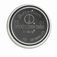
Serial Number iButton ABSOLUTE MAXIMUM RATINGS IO Voltage Range to GND .....................................-0.5V to +6.0V IO Sink Current....................................................................20mA Stresses beyond those listed under “Absolute Maximum Ratings” may cause permanent damage to the device. These are stress ratings only, and functional operation ...
Page 3
... SIZE See the Package Information section. WEIGHT (DS1990A) Ca. 2.5 grams Detailed Description The block diagram in Figure 1 shows the major function blocks of the device. The DS1990A takes the energy it needs to operate from the IO line, as indicated by the DS1990A IO Figure 1. Block Diagram _______________________________________________________________________________________ Serial Number iButton whenever the master drives the line low ...
Page 4
... Figure 3. 1-Wire CRC Generator 4 _______________________________________________________________________________________ The 1-Wire bus is a system that has a single bus master and one or more slaves. In all instances, the DS1990A is a slave device. The bus master is typically a micro- controller or PC. For small configurations, the 1-Wire communication signals can be generated under soft- ware control using a single port pin ...
Page 5
... The initialization sequence consists of a reset pulse transmitted by the bus master followed by presence pulse(s) transmitted by the slave(s). The presence pulse lets the bus master know that the DS1990A is on the bus and is ready to operate. For more details, see the 1-Wire Signaling section. V PUP ...
Page 6
... Match ROM and Skip ROM are not applicable. The DS1990A remains silent (inactive) upon receiving a ROM function command that it does not support. This allows the DS1990A to coexist on a multidrop bus with other 1-Wire devices that do respond to Match ROM or Skip ROM. ...
Page 7
... PUP the 1-Wire network attached. The initialization sequence required to begin any com- munication with the DS1990A is shown in Figure 6. A reset pulse followed by a presence pulse indicates that the DS1990A is ready to receive a ROM function com- mand. If the bus master uses slew-rate control on the falling edge, it must pull down the line for t compensate for the edge ...
Page 8
... IHMIN V ILMAX RESISTOR WRITE-ZERO TIME SLOT V PUP V IHMASTER V IHMIN V ILMAX RESISTOR READ-DATA TIME SLOT PUP V IHMASTER V IHMIN V ILMAX RESISTOR Figure 7. Read/Write Timing Diagram 8 _______________________________________________________________________________________ ε t SLOT MASTER t W0L t SLOT MASTER t MSR MASTER SAMPLING WINDOW δ t SLOT MASTER ε t REC t REC DS1990A ...
Page 9
... When responding with a 1, the DS1990A does not hold the data line low at all, and the voltage starts rising as soon For the latest package outline information and land patterns www.maxim-ic.com/packages. ...
Page 10
... Maxim cannot assume responsibility for use of any circuitry other than circuitry entirely embodied in a Maxim product. No circuit patent licenses are implied. Maxim reserves the right to change the circuitry and specifications without notice at any time. 10 ____________________Maxim Integrated Products, 120 San Gabriel Drive, Sunnyvale, CA 94086 408-737-7600 © 2008 Maxim Integrated Products DESCRIPTION specification ...