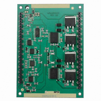
MSA260KC Cirrus Logic Inc, MSA260KC Datasheet - Page 7

MSA260KC
Manufacturer Part Number
MSA260KC
Description
AMP PWM 450V 20A 58-DIP KC
Manufacturer
Cirrus Logic Inc
Series
Apex Precision Power™r
Datasheet
1.MSA260KC.pdf
(8 pages)
Specifications of MSA260KC
Description/function
Audio Amplifiers
Package / Case
DIP-58
Product
Audio Modules
Lead Free Status / RoHS Status
Contains lead / RoHS non-compliant
For Use With
598-1469 - EVAL KIT FOR MSA240/MSA260
Lead Free Status / Rohs Status
Lead free / RoHS Compliant
Other names
598-1417
MSA260KC
MSA260KC
DeterMininG the oUtpUt StAte
The input signal is applied to +IN (Pin 13) and varies from 1.5 to 3.5 volts, zero to full scale. The ramp also varies
over the same range. When:
5% to 95% at 10kHz and 7% to 93% at 50kHz.
cAlcUlAtinG internAl poWer DiSSipAtion
Detailed calculation of internal power dissipation is complex but can be approximated with simple equations. Con-
duction loss is given by:
where I = output current
Switching loss is given by:
Combine these two losses to obtain total loss. Calculate heatsink ratings and case temperatures as would be done
for a linear amplifier. For calculation of junction temperatures, assume half the loss is dissipated in each of two
switches:
RØhs = heatsink rating
RØjc = junction-to-case thermal resistance of the MSA260.
The SOA typical performance graphs below show performance with the MSA260 mounted with thermal grease on
the Cirrus HS26. The Free Air graph assumes vertical orientation of the heatsink and no obstruction to air flow in an
ambient temperature of 30°C. The other two graphs show performance with two levels of forced air. Note that air
velocity is given in linear feet per minute. As fans are rated in cubic delivery capability, divide the cubic rating by the
square area this air flows through to find velocity. As fan delivery varies with static pressure, these calculations are
approximations, and heatsink ratings vary with amount of power dissipated, there is no substitute for temperature
measurements on the heatsink in the center of the amplifier footprint as a final check.
MSA260U
The output duty cycle extremes vary somewhat with switching frequency and are internally limited to approximately
Ramp > +IN A
W = I • 2.5 + I
W = 0.00046 • I • Vsupply • Fswitching (in kHz)
Tj = Ta + Wtotal • RØhs + 1/2Wtotal • RØjc, where:
P r o d u c t I n n o v a t i o n F r o m
2
OUT
• 0.095
> B
OUT
MSA260


