LCD0821 Matrix Orbital, LCD0821 Datasheet - Page 12
LCD0821
Manufacturer Part Number
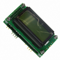
LCD0821
Description
LCD ALPHA/NUM DISPL 8X2 YW/GN BK
Manufacturer
Matrix Orbital
Series
LCD0821r
Datasheet
1.LCD0821.pdf
(29 pages)
Specifications of LCD0821
Display Type
TN - Twisted Nematic
Display Mode
Transmissive
Number Of Digits/alpha
16
Outline L X W X H
58.00mm x 32.00mm x 21.00mm
Viewing Area
38.00mm L x 16.00mm W
Backlight
LED - Yellow/Green
Display Format
8 x 2
Character Size
5.55mm H x 2.95mm W
Character Format
5 x 7 CURS
Voltage - Supply
5.0V
Dot Size
0.55mm W x 0.55mm H
Interface
I²C, RS232, TTL
Operating Temperature
0°C ~ 50°C
Character Count X Line
8 x 2
Module Size (w X H X T)
58 mm x 32 mm x 25 mm
Fluid Type
STN
Background Color
Yellow / Green
Backlight Type
LED Yellow / Green
Lead Free Status / RoHS Status
Lead free / RoHS Compliant
Other names
635-1009
LCD082
LCD082
Available stocks
Company
Part Number
Manufacturer
Quantity
Price
Company:

Part Number:
LCD0821
Manufacturer:
Matrix Orbital
Quantity:
135


The LCD0821 uses a standard Phillips 7bit address as defined by Phillips. How ever, we at Matrix Orbital
2
th
specify I
C address in 8bits. The 8
bit, least significant bit (LSB or Low Order Bit) of the 8bit address is
read/write bit. If we take a standard Phillips 7bit address of 45hex this would be in binary 1000101. This is
7bits. If one adds the read write bit to this 7bit address and you assume that you are writing one gets
2
10001010. Matrix Orbital would describe the Philips I
C address of 45hex as 8Ahex. The read address
would be 8Bhex.
2
For more information on Phillips I
C please visit…
http://www.ping.be/~ping0751/i2cfaq/i2cindex.htm
2.2 General Purpose Output
The LCD0821 has a general purpose output which can be used to control relays or other electronic devices.
This allows external devices to be turned on or off using your PC or controller and software commands.
(See sections 5.1.5 and 5.1.6 for the command syntax.)
The output is wired as shown in Figure 2-. The + terminal is connected to the module positive supply, the –
terminal is connected through a 240 ohm current limiting resistor and the electronic switch to ground.
+ 5 VDC
-
+
load
240 ohm current limiting resistor
Figure 2-10 General Purpose Outputs
Maximum allowable current is 20 mA, which is enforced by the current limiting resistor. If the device being
switched has a resistance of 240 ohms or more the corresponding resistor may be shorted. Solder a small
jumper wire (wirewrap wire is good) between the two feedthrough holes as shown in Figure 2-11.
LCD0821 rev 2
12
Related parts for LCD0821
Image
Part Number
Description
Manufacturer
Datasheet
Request
R

Part Number:
Description:
DISPLAY
Manufacturer:
Matrix Orbital
Datasheet:

Part Number:
Description:
LCD ACCY VFD FILTER 20X2 BLUE
Manufacturer:
Matrix Orbital
Datasheet:
Part Number:
Description:
LCD ACCY VFD FILTER 20X2 RED
Manufacturer:
Matrix Orbital
Datasheet:
Part Number:
Description:
LCD ACCY VFD FILTER 20X2 GREEN
Manufacturer:
Matrix Orbital
Datasheet:
Part Number:
Description:
LCD ACCY VFD FILTER 20X4 BLUE
Manufacturer:
Matrix Orbital
Datasheet:
Part Number:
Description:
LCD ACCY VFD FILTER 20X4 RED
Manufacturer:
Matrix Orbital
Datasheet:
Part Number:
Description:
LCD ACCY VFD FILTER 20X4 GREEN
Manufacturer:
Matrix Orbital
Datasheet:

Part Number:
Description:
DISPLAY
Manufacturer:
Matrix Orbital
Datasheet:

Part Number:
Description:
DISPLAY
Manufacturer:
Matrix Orbital
Datasheet:


Part Number:
Description:
VFD DISPLAY 16X2 SER/I2C
Manufacturer:
Matrix Orbital
Datasheet:

Part Number:
Description:
VFD ALPHA/NUM DISPL 20X2 SER/I2C
Manufacturer:
Matrix Orbital
Datasheet:

Part Number:
Description:
VFD ALPHA/NUM DISPL 16X2 SER/I2C
Manufacturer:
Matrix Orbital
Datasheet:
Part Number:
Description:
VFD ALPHA/NUM DISPL 20X2 SER/I2C
Manufacturer:
Matrix Orbital
Datasheet: