HCMS-2914 Avago Technologies US Inc., HCMS-2914 Datasheet - Page 14
HCMS-2914
Manufacturer Part Number
HCMS-2914
Description
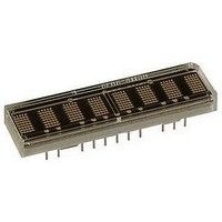
LED DISPLAY 5X7 8CHAR 3.8MM ORN
Manufacturer
Avago Technologies US Inc.
Series
HCMS-29xxr
Datasheet
1.HCMS-2903.pdf
(16 pages)
Specifications of HCMS-2914
Millicandela Rating
*
Size / Dimension
1.40" L x 0.40" W x 0.20" H (35.6mm x 10.2mm x 5.1mm)
Color
Orange
Configuration
5 x 7
Voltage - Forward (vf) Typ
*
Package / Case
26-DIP
Display Type
Alphanumeric
Number Of Digits/alpha
8
Digit/alpha Size
0.15" (3.8mm)
Character Format
Dot Matrix
Character Size
3.81mm
Led Color
Orange
Luminous Intensity
64µcd
No. Of Digits / Alpha
8
Display Area Width
35.56mm
Display Area Height
10.16mm
Number Of Digits
8
Illumination Color
Orange
Wavelength
600 nm
Operating Voltage
- 0.3 V to 5.5 V
Maximum Operating Temperature
+ 85 C
Minimum Operating Temperature
- 40 C
Lead Free Status / RoHS Status
Lead free / RoHS Compliant
Common Pin
-
Lead Free Status / Rohs Status
Details


Appendix A. Thermal Considerations
The display IC has a maximum junction temperature of
150°C. The IC junction temperature can be calculated
with Equation 1 below.
A typical value for Rq
for a display mounted in a socket and covered with a
plastic filter. The socket is soldered to a .062 in. thick PCB
with .020 inch wide, one ounce copper traces.
P
Figure 4 shows how to derate the power of one IC versus
ambient temperature. Operation at high ambient tem-
peratures may require the power per IC to be reduced.
The power consumption can be reduced by changing
either the N, I
very little impact on the power consumption.
Appendix B. Electrical Considerations
14
D
can be calculated as Equation 2 below.
Equation 1:
T
Where:
Equation 2:
P
Where:
Duty Factor = 1/8 * Osccyc/64
Equation 3:
I
Where:
Equation 4:
I
(see Variable Definitions above)
PEAK
LED
J
D
MAX = T
= (N * I
(AVG) = N * I
= M * 20 * I
Osc cyc = number of ON oscillator cycles per row
T
I
I
V
PIXEL
I
PEAK
J
I
LOGIC
LOGIC
MAX = maximum IC junction temperature
Rq
PIXEL
20 = maximum number of LEDs on per IC
PIXEL
M = number of ICs in the system
A
PIXEL
P
P
T
+ P
JA
N = number of pixels on (maximum 4 char * 5 * 7 = 140)
= maximum instantaneous peak current for the display
= peak current for one LED
A
D
D
= ambient temperature surrounding the display
= thermal resistance from the IC junction to ambient
= power dissipated by the IC
= total power dissipation
= peak pixel current.
= IC logic current
= logic supply voltage
, Osc cyc or V
* Duty Factor * V
D
* Rq
PIXEL
PIXEL
JA
is 100°C/W. This value is typical
* 1/8 * (oscillator cycles)/64
JA
LED
. Changing V
LED
) + I
LOGIC
* V
LOGIC
LOGIC
has
Figure 4.
1.3
1.2
1.1
1.0
0.9
0.8
0.7
0.6
0.5
0.4
0.3
0.2
0.1
0
25
30
T
35
A
– AMBIENT TEMPERATURE – °C
40
45
50
55
R
60
θ
J-A
65
= 100°C/W
70
75
80
85
90
Related parts for HCMS-2914
Image
Part Number
Description
Manufacturer
Datasheet
Request
R

Part Number:
Description:
LED DISPLAY 5X7 4CHAR 5MM GREEN
Manufacturer:
Avago Technologies US Inc.
Datasheet:

Part Number:
Description:
LED DISPLAY 5X7 8CHAR 3.8MM YLW
Manufacturer:
Avago Technologies US Inc.
Datasheet:

Part Number:
Description:
LED DISPLAY 5X7 4CHAR 3.8MM YLW
Manufacturer:
Avago Technologies US Inc.
Datasheet:

Part Number:
Description:
LED DISPLAY 5X7 4CHAR 3.8MM ORN
Manufacturer:
Avago Technologies US Inc.
Datasheet:

Part Number:
Description:
LED DISPL 5X7 4CHAR 3.8MM ALGAAS
Manufacturer:
Avago Technologies US Inc.
Datasheet:
Part Number:
Description:
LED DISPLAY 5X7 4CHAR 3.8MM RED
Manufacturer:
Avago Technologies US Inc.
Datasheet:
Part Number:
Description:
LED DISPLAY 5X7 4CHAR 3.8MM ORN
Manufacturer:
Avago Technologies US Inc.
Datasheet:
Part Number:
Description:
LED DISPLAY 5X7 4CHAR 3.8MM YLW
Manufacturer:
Avago Technologies US Inc.
Datasheet:
Part Number:
Description:
LED DISPLAY 5X7 4CHAR 5MM YLW
Manufacturer:
Avago Technologies US Inc.
Datasheet:
Part Number:
Description:
LED DISPLAY 5X7 4CHAR 5MM ORN
Manufacturer:
Avago Technologies US Inc.
Datasheet:
Part Number:
Description:
LED DISPLAY 5X7 4CHAR 5MM GRN
Manufacturer:
Avago Technologies US Inc.
Datasheet:
Part Number:
Description:
LED DISPLAY 5X7 4CHAR 5MM RED
Manufacturer:
Avago Technologies US Inc.
Datasheet:
Part Number:
Description:
LED DISPLAY 5X7 4CHAR 3.8MM RED
Manufacturer:
Avago Technologies US Inc.
Datasheet:
Part Number:
Description:
LED DISPLAY 5X7 4CHAR 3.8MM GRN
Manufacturer:
Avago Technologies US Inc.
Datasheet:
Part Number:
Description:
LED DISPLAY 5X7 4CHAR 5MM GRN
Manufacturer:
Avago Technologies US Inc.
Datasheet: