IPD2548A OSRAM Opto Semiconductors Inc, IPD2548A Datasheet
IPD2548A
Specifications of IPD2548A
Available stocks


Related parts for IPD2548A


IPD2548A Summary of contents
Page 1
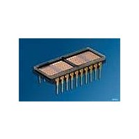
... Color of Emission IPD2545A high efficiency red IPD2547A green IPD2548A yellow 2006-03-03 (see page 10) IPD2545A IPD2547A IPD2548A FEATURES • Four 6.4 mm (0.252") Dot Matrix Characters in Hermetic Package four digit, High • Built-in Memory, Decoders, Multiplexer and Drivers • Viewing Angle, X axis ± 40°, Y axis ± 75° ...
Page 2
... YYWW Z Part No. Intensity Code Pin 1 EIA Date Code Symbol stg θ IPD2545A, IPD2547A, IPD2548A Dimensions in mm (inch) 1) 12.7 (0.500) 1) Tolerance: 0.254 (0.010) 2) Tolerance: 0.127 (0.005) IDOD5208 Value – 55 … +100 – 65 … +125 -0.5 to +6 Unit ° ...
Page 3
... These waveforms are not edge triggered. +25°C Max. Min. Typ. Max. 10 — 2.0 5.0 250 — 160 190 120 — 60 100 — 2.0 — — 0.8 — — 0.8 3 IPD2545A, IPD2547A, IPD2548A T CES ACC T CES T AS DATA OUT RACC =0 =2 +100°C Units Min. ...
Page 4
... Symbol Min ave λ — peak λ — dom =5.0 V and T =25°C unless otherwise noted IPD2545A, IPD2547A, IPD2548A 4) Typ. Units Test Conditions 150 µ sign ’’ON’’ on all CC digits at full brightness, T =25°C A 635 nm — 626 nm — ...
Page 5
... Chip enable (active low Address input (MSB Address input Address input (LSB). 10 GND Ground. 2006-03-03 IPD2545A, IPD2547A, IPD2548A Pin Function Definition 11 WR Write. Active low. If the device is selected, a low on the write input loads the data into memory Data Bus bit 7 (MSB Data Bus bit 6 ...
Page 6
... Data out voltages are measured with 100 pF on the data bus and the ability to source = –40 µA and sink=1.6 mA The rise and fall times are 60 ns 2006-03-03 =4.5 V) =4 IPD2545A, IPD2547A, IPD2548A Specification Minimum –55°C +25°C +100°C 1.0 1.0 1.0 1.0 1.0 1.0 10 ...
Page 7
... None the control lines. X None X None 1 None IPD2545A, IPD2547A, IPD2548A Operation Change Read Digit 0 Data to Bus ($) Written to Digit (W) Written to Digit (f) Written to Digit (3) Written to Digit Char. Written to Digit 0 and Cursor Enabled ...
Page 8
... Blink character 1 0 Display blinking cursor instead of character 1 1 Alternate character with cursor D4 Attribute Enable 0 Disable above attributes 1 Enable above attributes D5 Blink 0 Blink attribute disabled 1 Blink entire display Lamp Test Standard operation Display all dots at 50% brightness 8 IPD2545A, IPD2547A, IPD2548A ...
Page 9
... For larger displays, distribute the bypass capacitors evenly, keep- ing capacitors as close to the power pins as possible. We recom- mend a 10 µF and 0.01 µF for every Intelligent Display to decouple the displays themselves, at the display. 0.01 µF 10 µF 9 IPD2545A, IPD2547A, IPD2548A ...
Page 10
... Additionally, the following Power Up and Power Down sequence should be observed. RoHS Compliance The IPD2547A, IPD2545A, IPD2548A Intelligent Displays hermetically sealed displays using a ceramic and glass construc- tion. These components are not lead (Pb) free but are RoHS Com- pliant based on the RoHS Compliance Directive's Annex, paragraphs 5 and 7 ...
Page 11
... Turn off the power to the display. Character Set ASCII CODE HEX Notes: 1.High=1 level 2.Low=0 level 3.Upon power up, the device will initialize in a random state. 4.A2 must be held high for ASCII data. 5.Bit D7=1 enables attributes for the assigned digit. 2006-03- IPD2545A, IPD2547A, IPD2548A IDCS5087 ...
Page 12
... Life support devices or systems are intended ( implanted in the human body, or (b) to support and/or maintain and sustain human life. If they fail reasonable to assume that the health and the life of the user may be endangered. 2006-03-03 IPD2545A, IPD2547A, IPD2548A 2) with the express written approval of OSRAM OS. ...