HFBR-2526Z Avago Technologies US Inc., HFBR-2526Z Datasheet - Page 3
HFBR-2526Z
Manufacturer Part Number
HFBR-2526Z
Description
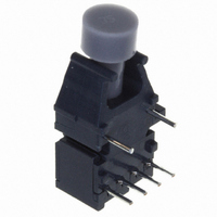
125MBD 650NM RECEIVER IN HORIZ
Manufacturer
Avago Technologies US Inc.
Specifications of HFBR-2526Z
Voltage - Supply
0.8 V ~ 2.6 V
Power - Minimum Receivable
-9.4dBm
Current - Supply
15mA
Applications
General Purpose
Data Rate Max
115Kbps
Data Transmission Distance
50ft
Wavelength Typ
660nm
Msl
MSL 4 - 72 Hours
Peak Reflow Compatible (260 C)
Yes
Fiber Material
Plastic
Leaded Process Compatible
Yes
Lead Free Status / RoHS Status
Lead free / RoHS Compliant
Data Rate
-
Lead Free Status / RoHS Status
Lead free / RoHS Compliant, Lead free / RoHS Compliant
Other names
516-1747
HFBR-2526Z
Q2636587A
HFBR-2526Z
Q2636587A
Available stocks
Company
Part Number
Manufacturer
Quantity
Price
Company:

Part Number:
HFBR-2526Z
Manufacturer:
Avago Technologies US Inc.
Quantity:
135
Company:
Part Number:
HFBR-2526Z
Manufacturer:
AVAGO
Quantity:
1 400


3
Plastic Optical Fiber (1 mm POF) Transmitter Application Circuit: Performance of the HFBR-15X7Z transmitter in the recom-
mended application circuit (Figure 1) for POF; 1-125 MBd, 25°C.
Hard Clad Silica Fiber (200 µm HCS) Transmitter Application Circuit: Performance of the HFBR-15X7Z transmitter in the recom-
mended application circuit (Figure 1) for HCS; 1-125 MBd, 25°C.
Notes:
1. Average optical power is measured with an average power meter at 50% duty cycle, after 1 meter of fiber.
2. To allow the LED to switch at high speeds, the recommended drive circuit modulates LED light output between two non-zero power levels.
3. High and low level LED currents refer to the current through the HFBR-15X7Z LED. The low level LED “off” current, sometimes referred to as
Parameter
Average Optical Power 1 mm POF
Average Modulated Power 1 mm POF
Optical Rise Time (10% to 90%)
Optical Fall Time (90% to 10%)
High Level LED Current (On)
Low Level LED Current (Off )
Optical Overshoot - 1 mm POF
Transmitter Application Circuit
Current Consumption - 1 mm POF
Parameter
Average Optical Power 200 µm HCS
Average Modulated Power 200 µm HCS
Optical Rise Time (10% to 90%)
Optical Fall Time (90% to 10%)
High Level LED Current (On)
Low Level LED Current (Off)
Optical Overshoot - 200 µm HCS
Transmitter Application Circuit
Current Consumption - 200 µm HCS
The modulated (useful) power is the difference between the high and low level of light output power (transmitted) or input power (received),
which can be measured with an average power meter as a function of duty cycle (see Figure 3). Average Modulated Power is defined as one
half the slope of the average power versus duty cycle:
“hold-on” current, is prebias supplied to the LED during the off state to facilitate fast switching speeds.
Average Modulated Power =
Symbol
P
P
I
I
I
Symbol
mod
t
t
avg
F,H
F,L
CC
[P
r
f
P
P
I
I
I
avg
mod
t
F,H
t
F,L
CC
avg
r
f
@ 80% duty cycle - P
Typical
-11.3
-9.7
110
2.1
2.8
19
45
3
Typical
-14.6
-16.2
130
(2) [0.80 - 0.20]
3.1
3.4
60
30
6
avg
@ 20% duty cycle]
dBm
dBm
Unit
mA
mA
mA
ns
ns
%
dBm
dBm
Unit
mA
mA
mA
ns
ns
%
50% Duty
Condition
50% Duty
Condition
5 MHz
5 MHz
Cycle
5 MHz
5 MHz
Cycle
Note 1, Fig 3
Note 2, Fig 3
Note 1, Fig 3
Note 2, Fig 3
Figure 1
Figure 1
Note 3
Note 3
Note 3
Note 3
Note
Note
Related parts for HFBR-2526Z
Image
Part Number
Description
Manufacturer
Datasheet
Request
R

Part Number:
Description:
RECEIVER FIBER OPTIC 600NM 5MBD
Manufacturer:
Avago Technologies US Inc.
Datasheet:

Part Number:
Description:
RECEIVER FIBER OPTIC 5MBD TTL ST
Manufacturer:
Avago Technologies US Inc.
Datasheet:

Part Number:
Description:
RCVR FIBER OPTIC INTERBUS-S
Manufacturer:
Avago Technologies US Inc.
Datasheet:

Part Number:
Description:
RCVR OPT HI PERF VERS LINK HORZ
Manufacturer:
Avago Technologies US Inc.
Datasheet:
Part Number:
Description:
RCVR OPT HI PERF VERS LINK HORZ
Manufacturer:
Avago Technologies US Inc.
Datasheet:

Part Number:
Description:
RECEIVER FIBER OPTIC 600NM 1MBD
Manufacturer:
Avago Technologies US Inc.
Datasheet:

Part Number:
Description:
RECEIVER FIBER OPTIC 600NM 1MBD
Manufacturer:
Avago Technologies US Inc.
Datasheet:

Part Number:
Description:
RECEIVER FIBER OPTIC VERT 1MBD
Manufacturer:
Avago Technologies US Inc.
Datasheet:

Part Number:
Description:
RECEIVER FIBER OPTIC 5MBD TTL ST
Manufacturer:
Avago Technologies US Inc.
Datasheet:

Part Number:
Description:
RECEIVER FIBER OPT 125MHZ ANA ST
Manufacturer:
Avago Technologies US Inc.
Datasheet:

Part Number:
Description:
OPTOCOUPLER GATE DRV 2A 16-SOIC
Manufacturer:
Avago Technologies US Inc.
Datasheet:
Part Number:
Description:
OPTOCOUPLER 2CH 2.5A 16-SOIC
Manufacturer:
Avago Technologies US Inc.
Datasheet:

Part Number:
Description:
OPTOCOUPLER GATE DRV 0.4A 16SOIC
Manufacturer:
Avago Technologies US Inc.
Datasheet:

Part Number:
Description:
OPTOCOUPLER 2.0A 250KHZ 8-DIP
Manufacturer:
Avago Technologies US Inc.
Datasheet:

Part Number:
Description:
OPTOCOUPLER 2.0A 250KHZ GW 8-SMD
Manufacturer:
Avago Technologies US Inc.
Datasheet: