HFBR-57E0PZ Avago Technologies US Inc., HFBR-57E0PZ Datasheet - Page 14
HFBR-57E0PZ
Manufacturer Part Number
HFBR-57E0PZ
Description
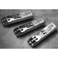
TXRX MM SFP LC CONN BAIL DELATCH
Manufacturer
Avago Technologies US Inc.
Series
-r
Specifications of HFBR-57E0PZ
Applications
Ethernet
Mounting Type
SFP
Voltage - Supply
2.97 V ~ 3.63 V
Connector Type
LC Duplex
Wavelength
1300nm
Data Rate
155MBd
Supply Voltage
3.3V
Wavelength Typ
1300nm
Leaded Process Compatible
Yes
Optical Fiber Type
TX/RX
Optical Rise Time
3/2.2ns
Optical Fall Time
3/2.2ns
Jitter
0.1/0.14ns
Operating Temperature Classification
Commercial
Peak Wavelength
1308/1380nm
Package Type
SFP
Operating Supply Voltage (min)
2.97V
Operating Supply Voltage (typ)
3.3V
Operating Supply Voltage (max)
3.63V
Output Current
50mA
Operating Temp Range
0C to 70C
Mounting
Snap Fit To Panel
Pin Count
20
Product
Transceiver
Maximum Rise Time
3 ns, 2.2 ns
Maximum Fall Time
3 ns, 2.2 ns
Pulse Width Distortion
0.1 ns, 0.14 ns
Maximum Output Current
50 mA
Operating Supply Voltage
2.97 V to 3.63 V
Maximum Operating Temperature
+ 70 C
Minimum Operating Temperature
0 C
Package / Case
SFP-20
Function
SFF Pluggable Transceivers with LC connector for ATM, FDDI, Fast Ethernet and SONET OC-3/SDH STM-1
Lead Free Status / RoHS Status
Lead free / RoHS Compliant
For Use With
Multimode Glass
Lead Free Status / RoHS Status
Lead free / RoHS Compliant, Lead free / RoHS Compliant
Available stocks
Company
Part Number
Manufacturer
Quantity
Price
Company:

Part Number:
HFBR-57E0PZ
Manufacturer:
Avago Technologies
Quantity:
135


Receiver Optical and Electrical Characteristics
HFBR-57E0LZ /PZ(T
HFBR-57E0ALZ/APZ (T
Notes:
11a. Systematic Jitter contributed by the transmitter is defined as the combination of Duty Cycle Distortion and Data Dependent Jitter.
11b. Duty Cycle Distortion contributed by the transmitter is measured at the 50% threshold of the optical output signal using an IDLE Line
11c. Data Dependent Jitter contributed by the transmitter is specified with the FDDI test pattern described in FDDI PMD Annex A.5.
12a. Random Jitter contributed by the transmitter is specified with a 155.52 MBd (77.5 MHz square-wave) input signal.
12b. Random Jitter contributed by the transmitter is specified with an IDLE Line State, 125 MBd (62.5 MHz square-wave) input signal. See
Parameter
Input Optical Power minimum at Window Edge
Input Optical Power at Eye Center
Input Optical Power Maximum
Duty Cycle Distortion Contributed by the Receiver
FE
Data Dependent Jitter Contributed by the Receiver
FE
Random Jitter Contributed by the Receiver
Loss of Signal - Deasserted
Loss of Signal - Asserted
Loss of Signal - Hysteresis
Loss of Signal Deassert Time (on to off)
Loss of Signal Assert Time (off to on)
Notes:
13a. This specification is intended to indicate the performance of the receiver section of the transceiver when Input Optical Power signal
14
Operating Wavelength
Systematic Jitter Contributed by the Receiver
OC-3
FE
OC-3
FE
OC-3
FE
OC-3
OC-3
FE
OC-3
FE
-
-
-
-
-
Systematic Jitter is measured at 50% threshold using a 155.52 MBd (77.5 MHz square-wave), 2
signal.
State, 125 MBd (62.5 MHz square-wave), input signal.
Application Information - Transceiver Jitter Performance Section of this data sheet for further details.
characteristics are present per the following definitions. The Input Optical Power dynamic range from the minimum level (with a window
time-width) to the maximum level is the range over which the receiver is guaranteed to provide output data with a Bit Error Rate (BER)
better than or equal to 1 x 10
At the Beginning of Life (BOL)
Over the specified operating temperature and voltage ranges
Input is a 155.52 MBd, 2
Appendix I.
Receiver data window time-width is 1.23 ns or greater for the clock recovery circuit to operate in. The actual test data window time-
width is set to simulate the effect of worst case optical input jitter based on the transmitter jitter values from the specification tables.
The test window time-width is 3.32 ns.
Transmitter operating with a 155.52 MBd, 77.5 MHz square-wave, input signal to simulate any cross-talk present between the transmitter
and receiver sections of the transceiver.
C
= 0 ºC to +70 ºC, V
C
= -40 ºC to +85 ºC, V
23
-1 PRBS data pattern with 72 “1” s and 72 “0”s inserted per the CCITT (now ITU-T) recommendation G.958
-10.
CC
P
P
P
DCD
DDJ
RJ
P
P
P
Symbol
SJ
l
IN MIN
IN MIN
IN MAX
A
D
A
= 2.97 V to 3.63 V)
- P
CC
D
(W)
(C)
= 2.97 V to 3.63 V)
Minimum
-14
-14
1270
P
-45
1.5
0
0
D
+ 1.5 dB
Typical
0.11
0.08
0.02
0.14
0.14
2
5
Maximum
-30
-31
-31
-31.8
1380
1.2
0.4
1.0
1.91
2.14
-31
-33
100
350
23
- 1 psuedorandom data pattern input
Units
dBm avg
dBm avg
dBm avg
nm
ns p-p
ns p-p
ns p-p
ns p-p
dBm avg
dBm avg
dB
µs
µs
Notes
13a, Figure 4
13b
14a, Figure 4
14b
13a
13b
15a
15b
15c
16a
16b
17
18
19
20
Related parts for HFBR-57E0PZ
Image
Part Number
Description
Manufacturer
Datasheet
Request
R

Part Number:
Description:
XMITTER OPTICAL 2MBD SERCOS
Manufacturer:
Avago Technologies US Inc.
Datasheet:
Part Number:
Description:
Fiber Optic Transmitters, Receivers, Transceivers SERCOS TRANSMITTER
Manufacturer:
Avago Technologies US Inc.

Part Number:
Description:
RECEIVER FIBER OPTIC 600NM 40KBD
Manufacturer:
Avago Technologies US Inc.
Datasheet:

Part Number:
Description:
XMITTER FIBER OPTIC 600NM 5MBD
Manufacturer:
Avago Technologies US Inc.
Datasheet:

Part Number:
Description:
XMITTER FIBER OPTIC 600NM 40KBD
Manufacturer:
Avago Technologies US Inc.
Datasheet:

Part Number:
Description:
XMITTER VERSATILE LINK HORZ
Manufacturer:
Avago Technologies US Inc.
Datasheet:

Part Number:
Description:
XMITTER OPT HI PERFORMANCE VERT
Manufacturer:
Avago Technologies US Inc.
Datasheet:

Part Number:
Description:
TXRX FIBER OPTIC 650NM 10MBAUD
Manufacturer:
Avago Technologies US Inc.
Datasheet:
Part Number:
Description:
TXRX FIBER OPTIC 650NM 10MBAUD
Manufacturer:
Avago Technologies US Inc.
Datasheet:

Part Number:
Description:
FIBER OPTIC TRANSMITTER 660NM
Manufacturer:
Avago Technologies US Inc.
Datasheet:

Part Number:
Description:
KIT EVAL FIBER OPTIC 5MBD
Manufacturer:
Avago Technologies US Inc.
Datasheet:
Part Number:
Description:
KIT EVAL FIBER OPTICS 32MBD
Manufacturer:
Avago Technologies US Inc.
Datasheet:

Part Number:
Description:
KIT EVAL FIBER OPTIC 5MBD
Manufacturer:
Avago Technologies US Inc.
Datasheet:

Part Number:
Description:
125MBd 1300nm FiberOptic Eval Kit
Manufacturer:
Avago Technologies US Inc.
Datasheet:

Part Number:
Description:
DC-5MBd 820nm FiberOptic EvalKit
Manufacturer:
Avago Technologies US Inc.
Datasheet: