HFBR-53A5VFMZ Avago Technologies US Inc., HFBR-53A5VFMZ Datasheet - Page 4
HFBR-53A5VFMZ
Manufacturer Part Number
HFBR-53A5VFMZ
Description
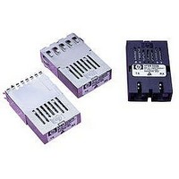
TXRX 1X9 3.3V GBE FLUSH SHIELD
Manufacturer
Avago Technologies US Inc.
Datasheet
1.HFBR-53A5VEMZ.pdf
(14 pages)
Specifications of HFBR-53A5VFMZ
Applications
Ethernet
Data Rate
1.25Gbd
Wavelength
850nm
Voltage - Supply
3.14 V ~ 3.47 V
Connector Type
SC
Mounting Type
Through Hole
Supply Voltage
3.3V
Wavelength Typ
850nm
Leaded Process Compatible
Yes
Lead Free Status / RoHS Status
Lead free / RoHS Compliant
Available stocks
Company
Part Number
Manufacturer
Quantity
Price
Company:

Part Number:
HFBR-53A5VFMZ
Manufacturer:
VISHAY
Quantity:
363


APPLICATION SUPPORT
Optical Power Budget and Link Penalties
The worst-case Optical Power Budget (OPB) in dB for
a fiber-optic link is determined by the difference be-
tween the minimum transmitter output optical power
(dBm avg) and the lowest receiver sensitivity (dBm
avg). This OPB provides the necessary optical signal
range to establish a working fiber-optic link. The OPB is
allocated for the fiber-optic cable length and the
corresponding link penalties. For proper link
performance, all penalties that affect the link
performance must be accounted for within the link
optical power budget. The Gigabit Ethernet IEEE 802.3z
standard identifies, and has modeled, the contributions
of these OPB penalties to establish the link length
requirements for 62.5/125 µm and 50/125 µm
multimode fiber usage. Refer to the IEEE 802.3z
standard and its supplemental documents that develop
the model, empirical results and final specifications.
Data Line Interconnections
Avago’s HFBR-53A5VEMZ/FMZ fiber-optic transceiver
is designed for compatible PECL signals. The transmit-
ter inputs are internally ac-coupled to the laser driver
circuit from the transmitter input pins (pins 7, 8). The
transmitter driver circuit for the laser light source is an
ac-coupled circuit. This circuit regulates the output
optical power. The regulated light output will maintain
a constant output optical power provided the data
pattern is reasonably balanced in duty factor. If the
data duty factor has long, continuous state times (low
or high data duty factor), then the output optical power
will gradually change its average output optical power
level to its pre-set value.
The receiver section is internally ac-coupled between
the pre-amplifier and the post-amplifier stages. The
actual Data and Data-bar outputs of the post-amplifier
are ac-coupled to their respective output pins (pins 2, 3).
Signal Detect is a single-ended, TTL output signal that
is dc-coupled to pin 4 of the module. Signal Detect
should not be ac-coupled externally to the follow-on
circuits because of its infrequent state changes.
Caution should be taken to account for the proper
interconnection between the supporting Physical
Layer integrated circuits and this HFBR-53A5VEMZ/FMZ
transceiver. Figure 3 illustrates a recommended
interface circuit for interconnecting to a dc PECL
compatible fiber-optic transceiver.
Eye Safety Circuit
For an optical transmitter device to be eye-safe in the
event of a single fault failure, the transmitter must either
maintain normal, eye-safe operation or be disabled.
In the HFBR-53A5VEMZ/FMZ there are three key
elements to the laser driver safety circuitry: a monitor
diode, a window detector circuit, and direct control of
the laser bias. The window detection circuit monitors
the average optical power using the monitor diode. If
a fault occurs such that the transmitter DC regulation
circuit cannot maintain the preset bias conditions for
the laser emitter within ±20%, the transmitter will
automatically be disabled. Once this has occurred,
only an electrical power reset will allow an attempted
turn-on of the transmitter.
Signal Detect
The Signal Detect circuit provides a deasserted output
signal that implies the link is open or the transmitter
is OFF as defined by the Gigabit Ethernet specification
IEEE 802.3z, Table 38.1. The Signal Detect threshold is
set to transition from a high to low state between the
minimum receiver input optional power and –30 dBm
avg. input optical power indicating a definite optical
fault (e.g., unplugged connector for the receiver or
transmitter, broken fiber, or failed far-end transmitter or
data source). A Signal Detect indicating a working link
is functional when receiving encoded 8B/10B
characters. The Signal Detect does not detect receiver
data error or error-rate. Data errors are determined
by Signal processing following the transceiver.
Electromagnetic Interference (EMI)
One of a circuit board designer’s foremost concerns is
the control of electromagnetic emissions from elec-
tronic equipment. Success in controlling gener-
ated Electromagnetic Interference (EMI) enables the
designer to pass a governmental agency’s EMI regulatory
standard; and more importantly, it reduces the
possibility of interference to neighboring equipment.
The EMI performance of an enclosure using these
transceivers is dependent on the chassis design. Avago
encourages using standard RF suppression practices
and avoiding poorly EMI-sealed enclosures.
Related parts for HFBR-53A5VFMZ
Image
Part Number
Description
Manufacturer
Datasheet
Request
R

Part Number:
Description:
FIBER OPTIC CBL SIMPLEX 1=100M
Manufacturer:
Avago Technologies US Inc.
Datasheet:

Part Number:
Description:
FIBER OPTIC CBL SIMPLEX 1=500M
Manufacturer:
Avago Technologies US Inc.
Datasheet:

Part Number:
Description:
FIBER OPTIC CONN LATCH GRY SIMPL
Manufacturer:
Avago Technologies US Inc.
Datasheet:

Part Number:
Description:
FIBER OPTIC CONN LATCH BLU SIMPL
Manufacturer:
Avago Technologies US Inc.
Datasheet:

Part Number:
Description:
HDWR V-LINK CONN CRIMPLESS BLACK
Manufacturer:
Avago Technologies US Inc.
Datasheet:

Part Number:
Description:
RECEIVER FIBER OPTIC 600NM 5MBD
Manufacturer:
Avago Technologies US Inc.
Datasheet:

Part Number:
Description:
RECEIVER FIBER OPTIC 600NM 10MBD
Manufacturer:
Avago Technologies US Inc.
Datasheet:

Part Number:
Description:
RECEIVER FIBER OPTIC 5MBD TTL ST
Manufacturer:
Avago Technologies US Inc.
Datasheet:

Part Number:
Description:
RECEIVER FIBER OPTIC 600NM 40KBD
Manufacturer:
Avago Technologies US Inc.
Datasheet:

Part Number:
Description:
RCVR MOD FIBER OPTIC SERCOS SMA
Manufacturer:
Avago Technologies US Inc.
Datasheet:
Part Number:
Description:
RCVR FIBER OPTIC INTERBUS-S
Manufacturer:
Avago Technologies US Inc.
Datasheet:

Part Number:
Description:
RCVR OPT HI PERF VERS LINK HORZ
Manufacturer:
Avago Technologies US Inc.
Datasheet:
Part Number:
Description:
RCVR OPT HI PERF VERS LINK HORZ
Manufacturer:
Avago Technologies US Inc.
Datasheet:

Part Number:
Description:
XMITTER FIBER OPTIC 600NM 5MBD
Manufacturer:
Avago Technologies US Inc.
Datasheet:

Part Number:
Description:
XMITTER FIBER OPTIC 600NM 40KBD
Manufacturer:
Avago Technologies US Inc.
Datasheet: