HFBR-53A5VFMZ Avago Technologies US Inc., HFBR-53A5VFMZ Datasheet - Page 7
HFBR-53A5VFMZ
Manufacturer Part Number
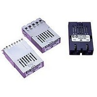
HFBR-53A5VFMZ
Description
TXRX 1X9 3.3V GBE FLUSH SHIELD
Manufacturer
Avago Technologies US Inc.
Datasheet
1.HFBR-53A5VEMZ.pdf
(14 pages)
Specifications of HFBR-53A5VFMZ
Applications
Ethernet
Data Rate
1.25Gbd
Wavelength
850nm
Voltage - Supply
3.14 V ~ 3.47 V
Connector Type
SC
Mounting Type
Through Hole
Supply Voltage
3.3V
Wavelength Typ
850nm
Leaded Process Compatible
Yes
Lead Free Status / RoHS Status
Lead free / RoHS Compliant
Available stocks
Company
Part Number
Manufacturer
Quantity
Price
Company:

Part Number:
HFBR-53A5VFMZ
Manufacturer:
VISHAY
Quantity:
363


HFBR-53A5VEMZ/FMZ, 850 nm VCSEL
Transmitter Optical Characteristics
(T
O utput Optical Power
50/125 µm, NA = 0.20 Fiber
Output Optical Power
62.5/125 µm, NA = 0.275 Fiber
Optical Extinction Ratio
Center Wavelength
Spectral Width – rms
O ptical Rise/Fall Time
RIN
C oupled Power Ratio
T otal Transmitter Jitter
Added at TP2
Receiver Optical Characteristics
(T
Input Optical Power
S tressed Receiver Sensitivity
S tressed Receiver Eye
O pening at TP4
Receive Electrical 3 dB
Upper Cutoff Frequency
Operating Center Wavelength
Return Loss
Signal Detect – Asserted
Signal Detect – Deasserted
Signal Detect – Hysteresis
Parameter
Parameter
Notes:
1. The maximum Optical Output Power complies with the IEEE 802.3z specification, and is class 1 laser eye safe.
2. Optical Extinction Ratio is defined as the ratio of the average optical power of the transmitter in the high (“1”) state to the low (“0”) state. Ex-
3. These are unfiltered 20-80% values.
4. Laser transmitter pulse response characteristics are specified by an eye diagram (Figure 1). The characteristics include rise time, fall time, pulse
5. CPR is measured in accordance with EIA/TIA-526-14A as referenced in 802.3z, section 38.6.10.
6. TP refers to the compliance point specified in 802.3z, section 38.2.1.
7. The receive sensitivity is measured using a worst case extinction ratio penalty while sampling at the center of the eye.
8. The stressed receiver sensitivity is measured using the conformance test signal defined in 802.3z, section 38.6.11. The conformance test signal is
9. The stressed receiver jitter is measured using the conformance test signal defined in 802.3z, section 38.6.11 and set to an average optical power
10. The 3 dB electrical bandwidth of the receiver is measured using the technique outlined in 802.3z, section 38.6.12.
11. Return loss is defined as the minimum attenuation (dB) of received optical power for energy reflected back into the optical fiber.
12. With valid 8B/10B encoded data.
A
A
= 0°C to +70°C, V
= 0°C to +70°C, V
tinction Ratio shall be measured using the methods specified in TIA/EIA.526.4A. This measurement may be made with the node transmitting
a 36A.3 data pattern. The Saturation Ratio is measured under fully modulated conditions with worst case reflections. A36A.3 data pattern is a
repeating K28.7 data pattern which generates a 125 mHz square wave.
overshoot, pulse undershoot, and ringing, all of which are controlled to prevent excessive degradation of the receiver sensitivity. These param-
eters are specified by the referenced Gigabit Ethernet eye diagram using the required filter. The output optical waveform complies with the
requirements of the eye mask discussed in section 38.6.5 and Fig. 38-2 of IEEE 802.3z.
conditioned by applying deterministic jitter and intersymbol interference.
0.5 dB greater than the specified stressed receiver sensitivity.
12
CC
CC
= 3.14 V to 3.47 V)
= 3.14 V to 3.47 V)
Symbol
P
62.5 µm
50 µm
λ
P
P
P
A
A
IN
C
D
– P
Symbol
P
P
λ
σ
t
CPR
r
OUT
OUT
C
/t
D
f
Min.
–17
201
770
12
–30
1.5
Min.
–9.5
–9.5
9
830
9
Typ.
Typ.
850
Max.
0
–12.5
–13.5
1500
860
–17
Max.
–4
–4
860
0.85
0.26
–117
227
Unit
dBm avg.
dBm avg.
dB
nm
nm rms
ns
dB/Hz
dB
ps
Unit
dBm avg.
dBm avg.
dBm avg.
ps
MHz
nm
dB
dBm avg.
dBm avg.
dB
Reference
1
1
2
3, 4, Figure 1
5
6
Reference
7
8
8
6, 9
10
11
12
12
12
Related parts for HFBR-53A5VFMZ
Image
Part Number
Description
Manufacturer
Datasheet
Request
R

Part Number:
Description:
FIBER OPTIC CBL SIMPLEX 1=100M
Manufacturer:
Avago Technologies US Inc.
Datasheet:

Part Number:
Description:
FIBER OPTIC CBL SIMPLEX 1=500M
Manufacturer:
Avago Technologies US Inc.
Datasheet:

Part Number:
Description:
FIBER OPTIC CONN LATCH GRY SIMPL
Manufacturer:
Avago Technologies US Inc.
Datasheet:

Part Number:
Description:
FIBER OPTIC CONN LATCH BLU SIMPL
Manufacturer:
Avago Technologies US Inc.
Datasheet:

Part Number:
Description:
HDWR V-LINK CONN CRIMPLESS BLACK
Manufacturer:
Avago Technologies US Inc.
Datasheet:

Part Number:
Description:
RECEIVER FIBER OPTIC 600NM 5MBD
Manufacturer:
Avago Technologies US Inc.
Datasheet:

Part Number:
Description:
RECEIVER FIBER OPTIC 600NM 10MBD
Manufacturer:
Avago Technologies US Inc.
Datasheet:

Part Number:
Description:
RECEIVER FIBER OPTIC 5MBD TTL ST
Manufacturer:
Avago Technologies US Inc.
Datasheet:

Part Number:
Description:
RECEIVER FIBER OPTIC 600NM 40KBD
Manufacturer:
Avago Technologies US Inc.
Datasheet:

Part Number:
Description:
RCVR MOD FIBER OPTIC SERCOS SMA
Manufacturer:
Avago Technologies US Inc.
Datasheet:
Part Number:
Description:
RCVR FIBER OPTIC INTERBUS-S
Manufacturer:
Avago Technologies US Inc.
Datasheet:

Part Number:
Description:
RCVR OPT HI PERF VERS LINK HORZ
Manufacturer:
Avago Technologies US Inc.
Datasheet:
Part Number:
Description:
RCVR OPT HI PERF VERS LINK HORZ
Manufacturer:
Avago Technologies US Inc.
Datasheet:

Part Number:
Description:
XMITTER FIBER OPTIC 600NM 5MBD
Manufacturer:
Avago Technologies US Inc.
Datasheet:

Part Number:
Description:
XMITTER FIBER OPTIC 600NM 40KBD
Manufacturer:
Avago Technologies US Inc.
Datasheet: