AFCT-5179AZ Avago Technologies US Inc., AFCT-5179AZ Datasheet - Page 3
AFCT-5179AZ
Manufacturer Part Number
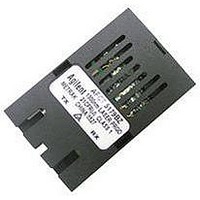
AFCT-5179AZ
Description
TXRX 125MBD DUPLEX BLACK SC 1X9
Manufacturer
Avago Technologies US Inc.
Datasheet
1.AFCT-5179BZ.pdf
(9 pages)
Specifications of AFCT-5179AZ
Applications
Ethernet
Data Rate
125MBd
Wavelength
1300nm
Voltage - Supply
*
Connector Type
SC
Mounting Type
Through Hole
Data Rate Max
0.125Gbps
Supply Voltage
5V
Wavelength Typ
1300nm
Leaded Process Compatible
Yes
Lead Free Status / RoHS Status
Lead free / RoHS Compliant


3
Functional Description
Receiver Section
Design
The receiver section contains an InGaAs/InP photo de-
tector and a preamplifier within the receptacle, coupled
to a postamplifier/decision circuit on a separate circuit
board.
The postamplifier is ac coupled to the preamplifier as
illustrated in Figure 1. The coupling capacitor is large
enough to pass the EFM test pattern at 125 MBd with-
out significant distortion or performance penalty.
Figure 1 also shows a filter network which limits
the bandwidth of the preamp output signal. The
filter is designed to bandlimit the preamp output
noise and thus improve the receiver sensitivity.
These components will also reduce the sensitivity of
the receiver as the signal bit rate is increased above 155
MBd.
Figure 1 - Receiver Block Diagram
V
Figure 2 - p Filter Network for Noise Filtering
Noise Immunity
The receiver includes internal circuit components to filter
power supply noise. Under some conditions of EMI and
power supply noise, external power supply filtering
may be necessary. If receiver sensitivity is found to be
degraded by power supply noise, the filter network illus-
trated in Figure 2 may be used to improve performance.
The values of the filter components are general recom-
mendations and may be changed to suit a particular
system environment. Shielded inductors are recom-
mended.
100 nF
RECEIVER
RECEPTACLE
CC
TRANS-
IMPEDANCE
PRE-
AMPLIFIER
3.3 µH
100 nF
GND
FILTERED V
+
10 µF
FILTER
CC
to DATA LINK
LIMITING
AMPLIFIER
CIRCUIT
SIGNAL
DETECT
Terminating the Outputs
The PECL Data outputs of the receiver may be termi-
nated with the standard Thevenin-equivalent 50 ohm
to V
Other standard PECL terminating techniques may be
used.
The two outputs of the receiver should be terminated
with identical load circuits to avoid unnecessarily large
ac current in V
the ac current is largely nulled. The Signal Detect out-
put of the receiver is PECL logic and must be loaded if
it is to be used. The Signal Detect circuit is much slower
than the data path, so the ac noise generated by an
asymmetrical load is negligible. Power consumption
may be reduced by using a higher than normal load
impedance for the Signal Detect output. Transmission
line effects are not generally a problem as the switching
rate is slow.
The Signal Detect Circuit
The Signal Detect circuit works by sensing the peak
level of the received signal and comparing this level to
a reference.
CC
- 2 V termination.
PECL
OUTPUT
BUFFER
PECL
OUTPUT
BUFFER
CC
. If the outputs are loaded identically
DATA OUT
DATA OUT
SD
Related parts for AFCT-5179AZ
Image
Part Number
Description
Manufacturer
Datasheet
Request
R

Part Number:
Description:
TXRX OPT 1X9 155MB/S 1300NM BK
Manufacturer:
Avago Technologies US Inc.
Datasheet:

Part Number:
Description:
TXRX OPT SFF PLUGGABLE BAIL
Manufacturer:
Avago Technologies US Inc.
Datasheet:
Part Number:
Description:
TXRX OPT SFF PLUGGABLE BAIL DMI
Manufacturer:
Avago Technologies US Inc.
Datasheet:

Part Number:
Description:
TXRX 125MBD DUPLEX BLACK SC 1X9
Manufacturer:
Avago Technologies US Inc.
Datasheet:
Part Number:
Description:
TXRX 125MBD DUPLEX BLUE SC 1X9
Manufacturer:
Avago Technologies US Inc.
Datasheet:

Part Number:
Description:
TXRX OPT SM 155MBS SONET OC3/SDH
Manufacturer:
Avago Technologies US Inc.
Datasheet:
Part Number:
Description:
TXRX SFF SM OC3/STM-1 BAIL DMI
Manufacturer:
Avago Technologies US Inc.
Datasheet:
Part Number:
Description:
TXRX 125MBD DUPLEX BLUE SC 1X9
Manufacturer:
Avago Technologies US Inc.
Datasheet:

Part Number:
Description:
TXRX OPT SM 155MBS SONET OC3/SDH
Manufacturer:
Avago Technologies US Inc.
Datasheet:

Part Number:
Description:
TXRX OPT SM 155MBS SONET OC3/SDH
Manufacturer:
Avago Technologies US Inc.
Datasheet:

Part Number:
Description:
OPTOCOUPLER GATE DRV 2A 16-SOIC
Manufacturer:
Avago Technologies US Inc.
Datasheet:
Part Number:
Description:
OPTOCOUPLER 2CH 2.5A 16-SOIC
Manufacturer:
Avago Technologies US Inc.
Datasheet:

Part Number:
Description:
OPTOCOUPLER GATE DRV 0.4A 16SOIC
Manufacturer:
Avago Technologies US Inc.
Datasheet:

Part Number:
Description:
OPTOCOUPLER 2.0A 250KHZ 8-DIP
Manufacturer:
Avago Technologies US Inc.
Datasheet:

Part Number:
Description:
OPTOCOUPLER 2.0A 250KHZ GW 8-SMD
Manufacturer:
Avago Technologies US Inc.
Datasheet: