HFBR-1527Z Avago Technologies US Inc., HFBR-1527Z Datasheet - Page 10
HFBR-1527Z
Manufacturer Part Number
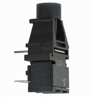
HFBR-1527Z
Description
FIBER OPTIC TX 125 MBD 650N
Manufacturer
Avago Technologies US Inc.
Specifications of HFBR-1527Z
Wavelength
650nm
Spectral Bandwidth
21nm
Voltage - Forward (vf) Typ
2.1V
Current - Dc Forward (if)
60mA
Voltage - Dc Reverse (vr) (max)
3V
Capacitance
60pF
Connector Type
Versatile Link
Function
Ideal for solving problems with voltage isolation/insulation, EMI/RFI immunity or data security.
Product
Transmitter
Data Rate
1 MBd, 125 MBd
Diode Capacitance
60 pF
Maximum Rise Time
12 ns (Typ)
Maximum Fall Time
9 ns (Typ)
Operating Supply Voltage
5.25 VDC
Maximum Operating Temperature
+ 70 C
Minimum Operating Temperature
0 C
Data Rate Max
1Mbps
Forward Current If
80mA
Forward Voltage
1.67V
Reverse Voltage Vr
5V
Data Transmission Distance
50ft
Wavelength Typ
660nm
Msl
MSL 4 - 72 Hours
Fiber Material
Plastic
Rohs Compliant
Yes
Lead Free Status / RoHS Status
Lead free / RoHS Compliant
For Use With
Plastic Optical Fiber, Hard Clad Silica
Lead Free Status / RoHS Status
Lead free / RoHS Compliant, Lead free / RoHS Compliant
Other names
516-1746
HFBR-1527Z
Q2636587
HFBR-1527Z
Q2636587
Available stocks
Company
Part Number
Manufacturer
Quantity
Price
Company:

Part Number:
HFBR-1527Z
Manufacturer:
AVAGO
Quantity:
1 400


10
Electrical/Optical Characteristics 0 to 70°C; 5.25 V ≥ V
Notes:
10. If there is no input optical power to the receiver (no transmitted signal) electrical noise can result in false triggering of the receiver. In typical
Parameter
AC Responsivity 1 mm POF
AC Responsivity 200 µm HCS
RMS Output Noise
Equivalent Optical Noise Input
Power, RMS - 1 mm POF
Equivalent Optical Noise Input
Power, RMS - 200 µm HCS
Peak Input Optical Power -
1 mm POF
Peak Input Optical Power -
200 µm HCS
Output Impedance
DC Output Voltage
Supply Current
Electrical Bandwidth
Bandwidth * Rise Time
Electrical Rise Time, 10-90%
Electrical Fall Time, 90-10%
Pulse Width Distortion
Overshoot
1. 1.6 mm below seating plane.
2. The signal output is an emitter follower, which does not reject noise in the power supply. The power supply must be filtered as in Figure 1.
3. Typical data are at 25°C and V
4. Pin 1 should be ac coupled to a load ≥ 510 Ω with load capacitance less than 5 pF.
5. Measured with a 3 pole Bessel filter with a 75 MHz, -3dB bandwidth.
6. The maximum Peak Input Optical Power is the level at which the Pulse Width Distortion is guaranteed to be less than the PWD listed under
7. 10 ns pulse width, 50% duty cycle, at the 50% amplitude point of the waveform.
8. Percent overshoot is defined at:
9. Pins 5 and 8 are primarily for mounting and retaining purposes, but are electrically connected. It is recommended that these pins be con-
Test Condition. P
MBd (for both POF and HCS input conditions).
nected to ground to reduce coupling of electrical noise.
applications, data encoding and error detection prevent random triggering from being interpreted as valid data. Refer to Application Note
1066 for design guidelines.
R,Max
is given for PWD = 5 ns for designing links at ≤ 50 MBd operation, and also for PWD = 2 ns for designing links up to 125
CC
= +5 Vdc.
Symbol
P
P
PWD
R
R
BW
V
N,RMS
N,RMS
Z
I
P,APF
P,HCS
P
P
V
t
t
CC
NO
O
O
r
f
R
R
E
CC
≥ 4.75 V; power supply must be filtered (see Figure 1, Note 2).
–––––––––––– × 100%
Min.
(V
1.7
4.5
0.8
65
PK
- V
V
100%
100%
0.46
0.41
Typ.
- 39
125
)
-42
3.9
7.9
1.8
3.3
3.3
0.4
30
9
4
Max.
11.5
0.69
-5.8
-6.4
-8.8
-9.4
-36
-40
6.5
2.6
6.3
6.3
1.0
15
mV/µW
mV/µW
mV
Hz * s
dBm
dBm
dBm
dBm
dBm
dBm
MHz
Unit
mA
ns
ns
ns
Ω
%
V
RMS
-3 dB electrical
Test Condition
P
P
P
P
R
R
R
R
5 ns PWD
2 ns PWD
5 ns PWD
2 ns PWD
P
650 nm
50 MHz
= -10 dBm
= -10 dBm
= -10 dBm
= -10 dBm
R
peak
peak
peak
peak
= 0 µW
Note 4
Note 5
Note 5
Note 5
Note 6
Note 6
Note 4
Note 7
Note 8
Note
Related parts for HFBR-1527Z
Image
Part Number
Description
Manufacturer
Datasheet
Request
R

Part Number:
Description:
XMITTER FIBER OPTIC SERCOS SMA
Manufacturer:
Avago Technologies US Inc.
Datasheet:

Part Number:
Description:
FIBER OPTIC CBL SIMPLEX 1=100M
Manufacturer:
Avago Technologies US Inc.
Datasheet:

Part Number:
Description:
FIBER OPTIC CBL SIMPLEX 1=500M
Manufacturer:
Avago Technologies US Inc.
Datasheet:

Part Number:
Description:
FIBER OPTIC CONN LATCH GRY SIMPL
Manufacturer:
Avago Technologies US Inc.
Datasheet:

Part Number:
Description:
FIBER OPTIC CONN LATCH BLU SIMPL
Manufacturer:
Avago Technologies US Inc.
Datasheet:

Part Number:
Description:
XMITTER VERSATILE LINK HORZ
Manufacturer:
Avago Technologies US Inc.
Datasheet:

Part Number:
Description:
Fiber Optic Transmitters, Receivers, Transceivers 1300nm 155MBd 16-pin DIP ST Rx
Manufacturer:
Avago Technologies US Inc.

Part Number:
Description:
FIBER OPTIC CBL DUPLEX 1=100M
Manufacturer:
Avago Technologies US Inc.
Datasheet:
Part Number:
Description:
FIBER OPTIC CBL SIMPLEX 1=500M
Manufacturer:
Avago Technologies US Inc.
Datasheet:
Part Number:
Description:
FIBER OPTIC CBL DUPLEX 1=500M
Manufacturer:
Avago Technologies US Inc.
Datasheet:

Part Number:
Description:
OPTOCOUPLER GATE DRV 2A 16-SOIC
Manufacturer:
Avago Technologies US Inc.
Datasheet:
Part Number:
Description:
OPTOCOUPLER 2CH 2.5A 16-SOIC
Manufacturer:
Avago Technologies US Inc.
Datasheet:

Part Number:
Description:
OPTOCOUPLER GATE DRV 0.4A 16SOIC
Manufacturer:
Avago Technologies US Inc.
Datasheet:

Part Number:
Description:
OPTOCOUPLER 2.0A 250KHZ 8-DIP
Manufacturer:
Avago Technologies US Inc.
Datasheet:

Part Number:
Description:
OPTOCOUPLER 2.0A 250KHZ GW 8-SMD
Manufacturer:
Avago Technologies US Inc.
Datasheet: