HFBR-1119TZ Avago Technologies US Inc., HFBR-1119TZ Datasheet
HFBR-1119TZ
Specifications of HFBR-1119TZ
Available stocks


Related parts for HFBR-1119TZ


HFBR-1119TZ Summary of contents
Page 1
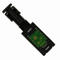
... Fiber Optic Transmitter and Receiver Data Links for 266 MBd Data Sheet Description The HFBR-1119TZ/-2119TZ series of data links are high-performance, cost-efficient, transmitter and receiver modules for serial optical data communication applications specified at 266 MBd for Fibre Channel applications or for general-purpose fiber optic data link transmission ...
Page 2
... MATERIAL PHOSPHOR BRONZE WITH 120 MICROINCHES TIN LEAD (90/10) OVER 50 MICROINCHES NICKEL. 3. UNITS = mm Figure 2. Package outline drawing. 2 PIN PHOTODIODE OPTICAL SIMPLEX ST SUBASSEMBLIES RECEPTACLE LED THREADS 3/8 – 32 UNEF-2A HFBR-111X/211XT DATE CODE (YYWW) SINGAPORE 12.19 MAX. 41 MAX. 5.05 0.9 2.45 19.72 17. 2.54 7.62 HOUSING PINS 0 ...
Page 3
OPTICAL PORT GND PIN NO PIN GND GND 5 CC GND 13 4 GND DATA 14 3 GND DATA ...
Page 4
... Vdc CC 5. INPUT OPTICAL RISE/FALL TIMES = 1.0/1.9 ns Figure 5. HFBR-1119TZ/2119TZ bit-error-ratio vs. relative receiver input optical power. The jitter specifications stated in the following transmitter and receiver specification tables are derived from the values in FC-PH Annex A.4.3 and A.4.4. They represent the worst-case jitter ...
Page 5
GND Vdc GND 0.1 13 GND DATA DATA 130 130 C5 0.1 TERMINATE D, D ...
Page 6
Board Layout–Hole Pattern The Avago transmitter and receiver hole pattern is compatible with other data link modules from other vendors. The drawing shown in Figure 7 can be used as a guide in the mechanical layout of your circuit board. ...
Page 7
... Infor- mation Technology Equipment. Additional information is available from your Avago sales representative. All HFBR-1119TZ LED trans- mitters are classified as IEC-825-1 Accessible Emission Limit (AEL) Class 1 based upon the current proposed draft scheduled to go into effect on January 1, 1997. AEL Class 1 LED devices are consid- ered eye safe ...
Page 8
... HFBR-1119TZ Transmitter Pin-Out Table Pin Symbol Functional Description internal connect, used for mechanical strength only GND Ground 4 GND Ground 5 GND Ground 6 GND Ground 7 OMIT No pin internal connect, used for mechanical strength only internal connect, used for mechanical strength only 10 GND Ground ...
Page 9
... Data Input Voltage Differential Input Voltage Output Current Recommended Operating Conditions Parameter Ambient Operating Temperature Supply Voltage Data Input Voltage–Low Data Input Voltage–High Data and Signal Detect Output Load HFBR-1119TZ Transmitter Electrical Characteristics ( 4 5 Parameter Supply Current Power Dissipation Threshold Voltage Data Input Current– ...
Page 10
... HFBR-1119TZ Transmitter Optical Characteristics ( 4 5 Parameter Output Optical Power 62.5/125 0.275 Fiber Output Optical Power 50/125 0.20 Fiber Optical Extinction Ratio Center Wavelength Spectral Width–FWHM Optical Rise Time Optical Fall Time Deterministic Jitter Contributed by the Transmitter Random Jitter Contributed by the ...
Page 11
Notes: 1. This is the maximum voltage that can be applied across the Differential Transmitter Data Inputs to prevent damage to the input ESD protection circuit. 2. When component testing these products, do not short the receiver Data or Signal ...
Page 12
For product information and a complete list of distributors, please go to our website: Avago, Avago Technologies, and the A logo are trademarks of Avago Technologies Limited in the United States and other countries. Data subject to change. Copyright © ...