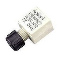
HFBR-1415Z Avago Technologies US Inc., HFBR-1415Z Datasheet - Page 11

HFBR-1415Z
Manufacturer Part Number
HFBR-1415Z
Description
XMITTER MINI HP FIB OPT ST PORT
Manufacturer
Avago Technologies US Inc.
Specifications of HFBR-1415Z
Wavelength
820nm
Voltage - Forward (vf) Typ
1.7V
Current - Dc Forward (if)
60mA
Voltage - Dc Reverse (vr) (max)
3.8V
Connector Type
ST
Data Rate Max
0.16Gbps
Supply Voltage
5V
Wavelength Typ
820nm
Leaded Process Compatible
Yes
Applications
100Base-SX Fast Ethernet, Media/Fiber Conversion, Switches, Routers, Hubs
Product
Transmitter
Data Rate
160 MBd
Diode Capacitance
55 pF
Operating Supply Voltage
7 VDC
Maximum Operating Temperature
+ 85 C
Minimum Operating Temperature
- 40 C
For Use With Fiber Type
Multimode
Function
High performance fiber optic communication links for information systems and industrial applications
Transmission Distance
2.7 Km
Lead Free Status / RoHS Status
Lead free / RoHS Compliant
Capacitance
-
Spectral Bandwidth
-
Lead Free Status / Rohs Status
Details
For Use With
Multimode Glass, Hard Clad Silica
Lead Free Status / RoHS Status
Lead free / RoHS Compliant, Lead free / RoHS Compliant
Available stocks
Company
Part Number
Manufacturer
Quantity
Price
Company:
Part Number:
HFBR-1415Z
Manufacturer:
Avago Technologies
Quantity:
135
5 MBd Logic Link Design
If resistor R1 in Figure 2 is 70.4 :, a forward current I
48 mA is applied to the HFBR-14x4Z LED transmitter. With
I
teed to work with 62.5/125 μm fiber optic cable over the
entire range of 0 to 1750 meters at a data rate of dc to 5
MBd, with arbitrary data format and pulse width distor-
tion typically less than 25%. By setting R
transmitter can be driven with I
to economize on power or achieve lower pulse distortion.
The following example will illustrate the technique for
selecting the appropriate value of I
+5 V
NOTE:
IT IS ESSENTIAL THAT A BYPASS CAPACITOR (0.01 μF TO 0.1 μF
CERAMIC) BE CONNECTED FROM PIN 2 TO PIN 7 OF THE RECEIVER.
TOTAL LEAD LENGTH BETWEEN BOTH ENDS OF THE CAPACITOR
AND THE PINS SHOULD NOT EXCEED 20 MM.
Figure 2. Typical Circuit Configuration.
11
F
DATA IN
= 48 mA the HFBR-14x4Z/24x2Z logic link is guaran-
1 K
SELECT R
R
R
½ 75451
1
1
=
=
R
1
233 Ω
V
1
CC
TO SET I
I
-
F
I
F
V
F
F
2
6
7
3
=
5V
TRANSMITTER
15
HFBR-14xxZ
T
-
mA
1.5V
F
= 30 mA, if it is desired
F
and R
1
1
= 115 :, the
.
F
of
TRANSMISSION
DISTANCE =
Maximum distance required = 400 meters. From Figure 3
the drive current should be 15 mA. From the transmitter
data V
The curves in Figures 3, 4, and 5 are constructed assum-
ing no inline splice or any additional system loss. Should
the link consists of any in-line splices, these curves can
still be used to calculate link limits provided they are
shifted by the additional system loss expressed in dB. For
example, Figure 3 indicates that with 48 mA of transmit-
ter drive current, a 1.75 km link distance is achievable
with 62.5/125 μm fiber which has a maximum attenua-
tion of 4 dB/km. With 2 dB of additional system loss, a
1.25 km link distance is still achievable.
F
= 1.5 V (max.) at I
F
= 15 mA as shown in Figure 9.
HFBR-24x2Z
RECEIVER
R
7 & 3
2
6
TTL DATA OUT
R
L
0.1 μF
V
CC


