HFBR-1521 Avago Technologies US Inc., HFBR-1521 Datasheet - Page 7
HFBR-1521
Manufacturer Part Number
HFBR-1521
Description
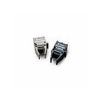
XMITTER VERSATILE LINK HORZ
Manufacturer
Avago Technologies US Inc.
Datasheet
1.HFBR-2521.pdf
(19 pages)
Specifications of HFBR-1521
Wavelength
600nm
Voltage - Forward (vf) Typ
1.67V
Current - Dc Forward (if)
60mA
Voltage - Dc Reverse (vr) (max)
5V
Capacitance
86pF
Connector Type
Versatile Link
Function
Ideal for solving problems with voltage isolation/insulation, EMI/RFI immunity or data security.
Product
Transmitter
Data Rate
5 MBd
Diode Capacitance
86 pF
Maximum Rise Time
80 ns
Maximum Fall Time
40 ns
Operating Supply Voltage
7 VDC
Maximum Operating Temperature
+ 85 C
Minimum Operating Temperature
- 40 C
For Use With
Plastic Optical Fiber
Lead Free Status / RoHS Status
Lead free / RoHS Compliant
Spectral Bandwidth
-
Lead Free Status / RoHS Status
Lead free / RoHS Compliant, Lead free / RoHS Compliant
Available stocks
Company
Part Number
Manufacturer
Quantity
Price

Part Number:
HFBR-1521
Manufacturer:
AVAGO/安华高
Quantity:
20 000
Part Number:
HFBR-1521ETZ HFBR-2521ETZ
Manufacturer:
AVAGO/安华高
Quantity:
20 000
Company:
Part Number:
HFBR-1521Z
Manufacturer:
Triquint
Quantity:
1 400
Company:
Part Number:
HFBR-1521Z
Manufacturer:
HFBR-1521Z
Quantity:
324


HFBR-15X1 Transmitter
Absolute Maximum Ratings
Notes:
1. 1.6 mm below seating plane.
2. Recommended operating range between 10 and 750 mA.
3. 1 s pulse, 20 s period.
7
All HFBR-15XX LED transmitters are classified as IEC 825-1 Accessible Emission Limit (AEL) Class 1
based upon the current proposed draft scheduled to go into effect on January 1, 1997. AEL Class 1 LED
devices are considered eye safe. Contact your local Avago sales representative for more information.
Parameter
Storage Temperature
Operating Temperature
Lead Soldering Cycle
Forward Input Current
Reverse Input Voltage
CATHODE
ANODE
N.C.
N.C.
1
2
3
4
8 DO NOT CONNECT
5 DO NOT CONNECT
Temp.
Time
Symbol
I
V
I
T
FPK
T
Fdc
BR
A
S
Min.
–40
–40
Note: Pins 5 and 8 are for mounting and retaining
purposes only. Do not electrically connect these pins.
Pin #
1
2
3
4
5
8
Max.
1000
+85
+85
260
10
80
5
Units
sec
mA
V
Function
Anode
Cathode
Open
Open
Do not connect
Do not connect
C
C
C
Reference
Note 1
Note 2, 3
Related parts for HFBR-1521
Image
Part Number
Description
Manufacturer
Datasheet
Request
R

Part Number:
Description:
FIBER OPTIC CBL SIMPLEX 1=100M
Manufacturer:
Avago Technologies US Inc.
Datasheet:

Part Number:
Description:
FIBER OPTIC CBL SIMPLEX 1=500M
Manufacturer:
Avago Technologies US Inc.
Datasheet:

Part Number:
Description:
FIBER OPTIC CONN LATCH GRY SIMPL
Manufacturer:
Avago Technologies US Inc.
Datasheet:

Part Number:
Description:
FIBER OPTIC CONN LATCH BLU SIMPL
Manufacturer:
Avago Technologies US Inc.
Datasheet:

Part Number:
Description:
XMITTER VERSATILE LINK HORZ
Manufacturer:
Avago Technologies US Inc.
Datasheet:

Part Number:
Description:
Fiber Optic Transmitters, Receivers, Transceivers 1300nm 155MBd 16-pin DIP ST Rx
Manufacturer:
Avago Technologies US Inc.

Part Number:
Description:
FIBER OPTIC CBL DUPLEX 1=100M
Manufacturer:
Avago Technologies US Inc.
Datasheet:
Part Number:
Description:
FIBER OPTIC CBL SIMPLEX 1=500M
Manufacturer:
Avago Technologies US Inc.
Datasheet:
Part Number:
Description:
FIBER OPTIC CBL DUPLEX 1=500M
Manufacturer:
Avago Technologies US Inc.
Datasheet:

Part Number:
Description:
FIBER OPTIC CBL SIMPLEX 1=100M
Manufacturer:
Avago Technologies US Inc.
Datasheet:

Part Number:
Description:
OPTOCOUPLER GATE DRV 2A 16-SOIC
Manufacturer:
Avago Technologies US Inc.
Datasheet:
Part Number:
Description:
OPTOCOUPLER 2CH 2.5A 16-SOIC
Manufacturer:
Avago Technologies US Inc.
Datasheet:

Part Number:
Description:
OPTOCOUPLER GATE DRV 0.4A 16SOIC
Manufacturer:
Avago Technologies US Inc.
Datasheet:

Part Number:
Description:
OPTOCOUPLER 2.0A 250KHZ 8-DIP
Manufacturer:
Avago Technologies US Inc.
Datasheet:

Part Number:
Description:
OPTOCOUPLER 2.0A 250KHZ GW 8-SMD
Manufacturer:
Avago Technologies US Inc.
Datasheet: