HFBR-1531 Avago Technologies US Inc., HFBR-1531 Datasheet
HFBR-1531
Specifications of HFBR-1531
Available stocks


Related parts for HFBR-1531


HFBR-1531 Summary of contents
Page 1
... Transmitters incorporate a 660 nm LED. Receivers include a monolithic dc coupled, digital IC receiver with open collector Schottky output transistor. An internal pullup resistor is available for use in the HFBR-25X1/2/4 receivers. A shield has been integrated into the receiver IC to provide additional, localized noise immunity. Internal optics have been optimized for use with 1 mm diameter plastic optical fiber ...
Page 2
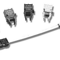
... HFBR-0501 1 MBd Versatile Link: This kit contains: HFBR-1524 Tx, HFBR-2524 Rx, polishing kit, 3 styles of plastic connectors, Bulkhead feedthrough, 5 meters diameter plastic cable, lapping film and grit paper, and HFBR-0501 data sheet. Application Literature Application Note 1035 (Versatile Link) Package and Handling Information The compact Versatile Link package is made of a flame ® ...
Page 3
Handling Versatile Link components are auto-insertable. When wave soldering is performed with Versatile Link components, the optical port plug should be left in to prevent contamination of the port. Do not use reflow solder processes (i.e., infrared reflow or vapor-phase ...
Page 4
Versatile Link Printed Board Layout Dimensions Horizontal Module 7.62 (0.300) 2.54 (0.100) 1.01 (0.040) DIA TOP VIEW 7.62 (0.300 1.85 MIN. (0.073) DIMENSIONS IN MILLIMETERS (INCHES). Interlocked (Stacked) Assemblies (refer to Figure 1) Horizontal ...
Page 5
... Figure 3. Guaranteed system performance with standard cable (HFBR-15X1/25X1) 5 Symbol Min. Typ. Max. Units Conditions dc 5 MBd 140 PLH t 50 140 PHL -15 dBm. 100 Figure 4. Guaranteed system performance with improved cable (HFBR-15X1/25X1) Ref BER 10 , PRBS Fig. 3 Fdc mA Note 3 Fdc Fig. 4 Fdc mA Note 3 Fdc 560 , Fig fiber length = 0 ...
Page 6
... P – INPUT OPTICAL POWER – dBm R Figure 7. Typical link pulse width distortion vs. optical power 6 500 400 t pLH HFBR-15X2/25X2 HFBR-15X4/25X4 300 200 HFBR-15X1/25X1 t pLH 100 t pHL 0 -25 -20 -15 - – INPUT OPTICAL POWER – dBm R Figure 8. Typical link propagation delay vs. optical power ...
Page 7
... Recommended operating range between 10 and 750 mA pulse period. All HFBR-15XX LED transmitters are classified as IEC 825-1 Accessible Emission Limit (AEL) Class 1 based upon the current proposed draft scheduled to go into effect on January 1, 1997. AEL Class 1 LED devices are considered eye safe. Contact your local Avago sales representative for more information. ...
Page 8
Transmitter Electrical/Optical Characteristics unless otherwise specified. Parameter Symbol Transmitter Output Optical Power Output Optical Power Temperature Coefficient Peak Emission Wavelength Forward Voltage Forward Voltage Temperature Coefficient Effective Diameter Numerical Aperture Reverse Input Breakdown Voltage Diode ...
Page 9
... HFBR-25X1 Receiver DO NOT CONNECT 5 1000 DO NOT CONNECT 8 Absolute Maximum Ratings Parameter Storage Temperature Operating Temperature Lead Soldering Cycle Temp. Time Supply Voltage Output Collector Current Output Collector Power Dissipation Output Voltage Pull-up Voltage Fan Out (TTL) Notes: 1. 1.6 mm below seating plane. ...
Page 10
... MBd Link (High Performance HFBR-15X2/25X2, Standard HFBR-15X4/25X4) System Performance Under recommended operating conditions unless otherwise specified. Parameter High Data Rate Performance Link Distance 1 MBd (Standard Cable) Link Distance (Improved Cable) Propagation Delay Pulse Width Distortion t -t PLH PHL Parameter Standard Data Rate ...
Page 11
... Figure 11. Required 1 MBd interface circuit The HFBR-25X2 receiver can not be overdriven when using the required interface circuit shown in Figure 11. 100 HFBR-15X4/25X4 30 0°C–70°C 25° – CABLE LENGTH – METRES Figure 12. Guaranteed system performance for the HFBR-15X4/25X4 Link with standard cable ...
Page 12
... P – INPUT OPTICAL POWER – dBm R Figure 17. Pulse width distortion vs. optical power Figure 19. Propagation delay test waveforms 12 500 400 t pLH HFBR-15X2/25X2 HFBR-15X4/25X4 300 200 HFBR-15X1/25X1 t pLH 100 t pHL 0 -25 -20 -15 - – INPUT OPTICAL POWER – dBm R Figure 18. Typical link propagation delay vs. optical power ...
Page 13
... Recommended operating range between 10 and 750 mA pulse period. All HFBR-15XX LED transmitters are classified as IEC 825-1 Accessible Emission Limit (AEL) Class 1 based upon the current proposed draft scheduled to go into effect on January 1, 1997. AEL Class 1 LED devices are considered eye safe. Contact your Avago sales representative for more information. ...
Page 14
... Measured at the end of the fiber optic cable with large area detector. 2. Pulsed LED operation at I > will cause increased link t F width distortion of the receiver output signal. 3. The LED drive circuit of Figure 11 is required for 1 MBd operation of the HFBR-25X2/25X4. 4. Optical flux, P (dBm Log [P( W)/1000 W open. L ...
Page 15
... CABLE LENGTH – METRES Figure 22. Guaranteed system performance with improved cable Ref PRBS Fig. 21 Fdc = 60 mA Note 1 Fdc = 2 mA Fig. 22 Fdc = 60 mA Note 1 Fdc = 3 Fig. 22 -25 dBm fiber Note dBm Fig HFBR-15X3/25X3 0°C–70°C 25° 100 110 ...
Page 16
Figure 23. 40 kBd propagation delay test circuit -40 -34 -28 -22 -16 -10 P – INPUT OPTICAL POWER, dBm R Figure 24. Typical link pulse width distortion vs. optical power Figure 26. ...
Page 17
... Recommended operating range between 10 and 750 mA pulse period. All HFBR-15XX LED transmitters are classified as IEC 825-1 Accessible Emission Limit (AEL) Class 1 based upon the current proposed draft scheduled to go into effect on January 1, 1997. AEL Class 1 LED devices are considered eye safe. Contact your Avago sales representative for more information. ...
Page 18
... Optical flux, P (dBm Log P( W)/1000 W. 3. Because of the very high sensitivity of the HFBR-25X3, the digital output may switch in response to ambient light levels when a cable is not occupying the receiver optical port. The designer should take care to filter out signals from this source if they pose a hazard to the system. ...
Page 19
For product information and a complete list of distributors, please go to our website: Avago, Avago Technologies, and the A logo are trademarks of Avago Technologies Limited in the United States and other countries. Data subject to change. Copyright © ...