VSMS3700-GS08 Vishay, VSMS3700-GS08 Datasheet - Page 5
VSMS3700-GS08
Manufacturer Part Number
VSMS3700-GS08
Description
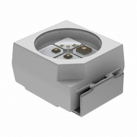
EMITTER IR PLCC-2 STD 950NM
Manufacturer
Vishay
Specifications of VSMS3700-GS08
Rise Time
800 ns
Radiant Intensity
4.5 mW/sr
Viewing Angle
120°
Current - Dc Forward (if)
100mA
Radiant Intensity (ie) Min @ If
1.6mW/sr @100mA
Wavelength
950nm
Voltage - Forward (vf) Typ
1.3V
Orientation
Top View
Mounting Type
Surface Mount
Package / Case
PLCC-2
Beam Angle
60 deg
Maximum Power Dissipation
170 mW
Maximum Operating Temperature
+ 85 C
Minimum Operating Temperature
- 40 C
Fall Time
800 ns
Forward Current
100 mA
Forward Voltage
1.3 V
Mounting Style
SMD/SMT
Peak Wavelength
950nm
Forward Current If(av)
100mA
Fall Time Tf
800ns
Supply Voltage Range
1.3V
Lead Free Status / RoHS Status
Lead free / RoHS Compliant
Lead Free Status / RoHS Status
Lead free / RoHS Compliant, Lead free / RoHS Compliant
Other names
751-1258-2
Available stocks
Company
Part Number
Manufacturer
Quantity
Price


SOLDER PROFILE
DRYPACK
Devices are packed in moisture barrier bags (MBB) to
prevent the products from moisture absorption during
transportation and storage. Each bag contains a desiccant.
FLOOR LIFE
Floor life (time between soldering and removing from MBB)
must not exceed the time indicated on MBB label:
Floor life: 168 h
Conditions: T
Moisture sensitivity level 3, acc. to J-STD-020.
DRYING
In case of moisture absorption devices should be baked
before soldering. Conditions see J-STD-020 or label.
Devices taped on reel dry using recommended conditions
192 h at 40 °C (+ 5 °C), RH < 5 %.
TAPE AND REEL
PLCC-2 components are packed in antistatic blister tape
(DIN IEC (CO) 564) for automatic component insertion.
Cavities of blister tape are covered with adhesive tape.
Document Number: 81373
Rev. 1.3, 03-Nov-09
Fig. 11 - Lead (Pb)-free Reflow Solder Profile acc. J-STD-020
Adhesive tape
19841
300
250
200
150
100
50
0
amb
0
255 °C
240 °C
217 °C
max. ramp up 3 °C/s max. ramp down 6 °C/s
Component cavity
< 30 °C, RH < 60 %
50
Fig. 12 - Blister Tape
max. 120 s
100
Time (s)
150
For technical questions, contact:
max. 100 s
max. 30 s
200
max. 260 °C
Blister tape
Infrared Emitting Diode, 950 nm,
250
245 °C
300
94 8670
GaAs
emittertechsupport@vishay.com
MISSING DEVICES
A maximum of 0.5 % of the total number of components per
reel may be missing, exclusively missing components at the
beginning and at the end of the reel. A maximum of three
consecutive components may be missing, provided this gap
is followed by six consecutive components.
The tape leader is at least 160 mm and is followed by a
carrier tape leader with at least 40 empty compartments.
The tape leader may include the carrier tape as long as the
cover tape is not connected to the carrier tape. The least
component is followed by a carrier tape trailer with a least
75 empty compartments and sealed with cover tape.
Tape leader
1.6
1.4
> 160 mm
Fig. 13 - Tape Dimensions in mm for PLCC-2
De-reeling direction
Fig. 14 - Beginning and End of Reel
4.1
3.9
3.5
3.1
Carrier leader
compartments
2.05
1.95
Vishay Semiconductors
40 empty
4.1
3.9
1.85
1.65
3.6
3.4
5.75
5.25
VSMS3700
Carrier trailer
8.3
7.7
min. 75 empty
compartments
www.vishay.com
0.25
2.2
2.0
94 8668
94 8158
4.0
3.6
326
Related parts for VSMS3700-GS08
Image
Part Number
Description
Manufacturer
Datasheet
Request
R

Part Number:
Description:
Infrared Emitting Diode, 950 Nm Rohs Compliant, Released For Lead Pb -free Solder Process
Manufacturer:
Vishay
Datasheet:
Part Number:
Description:
357-036-542-201 CARDEDGE 36POS DL .156 BLK LOPRO
Manufacturer:
Vishay
Datasheet:
Part Number:
Description:
357-036-542-201 CARDEDGE 36POS DL .156 BLK LOPRO
Manufacturer:
Vishay
Datasheet:
Part Number:
Description:
357-036-542-201 CARDEDGE 36POS DL .156 BLK LOPRO
Manufacturer:
Vishay
Datasheet:
Part Number:
Description:
357-036-542-201 CARDEDGE 36POS DL .156 BLK LOPRO
Manufacturer:
Vishay
Datasheet:
Part Number:
Description:
357-036-542-201 CARDEDGE 36POS DL .156 BLK LOPRO
Manufacturer:
Vishay
Datasheet:
Part Number:
Description:
357-036-542-201 CARDEDGE 36POS DL .156 BLK LOPRO
Manufacturer:
Vishay
Datasheet:
Part Number:
Description:
357-036-542-201 CARDEDGE 36POS DL .156 BLK LOPRO
Manufacturer:
Vishay
Datasheet:
Part Number:
Description:
357-036-542-201 CARDEDGE 36POS DL .156 BLK LOPRO
Manufacturer:
Vishay
Datasheet:
Part Number:
Description:
357-036-542-201 CARDEDGE 36POS DL .156 BLK LOPRO
Manufacturer:
Vishay
Datasheet:
Part Number:
Description:
357-036-542-201 CARDEDGE 36POS DL .156 BLK LOPRO
Manufacturer:
Vishay
Datasheet:
Part Number:
Description:
357-036-542-201 CARDEDGE 36POS DL .156 BLK LOPRO
Manufacturer:
Vishay
Datasheet:
Part Number:
Description:
357-036-542-201 CARDEDGE 36POS DL .156 BLK LOPRO
Manufacturer:
Vishay
Datasheet:
Part Number:
Description:
357-036-542-201 CARDEDGE 36POS DL .156 BLK LOPRO
Manufacturer:
Vishay
Datasheet: