HSMG-A100-J02J1 Avago Technologies US Inc., HSMG-A100-J02J1 Datasheet - Page 7
HSMG-A100-J02J1
Manufacturer Part Number
HSMG-A100-J02J1
Description
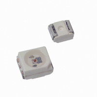
LED 565NM YLW-GRN WTR CLR 2-PLCC
Manufacturer
Avago Technologies US Inc.
Type
Uni-Colorr
Datasheet
1.HSMS-A100-J00J1.pdf
(12 pages)
Specifications of HSMG-A100-J02J1
Package / Case
2-PLCC
Viewing Angle
120°
Color
Green-Yellow
Luminous Flux @ Current - Test
57 mlm
Millicandela Rating
18mcd
Current - Test
20mA
Wavelength - Dominant
569nm
Wavelength - Peak
565nm
Voltage - Forward (vf) Typ
2.2V
Lens Type
Clear
Lens Style/size
Round, 2.4mm
Size / Dimension
3.20mm L x 2.80mm W
Height
1.90mm
Mounting Type
Surface Mount
Resistance Tolerance
569nm
Led Size
3.2 mm x 2.8 mm
Illumination Color
Yellow-Green
Operating Voltage
2.2 V
Wavelength
569 nm
Luminous Intensity
18 mcd
Mounting Style
SMD/SMT
Operating Current
20 mA
Maximum Operating Temperature
+ 100 C
Minimum Operating Temperature
- 55 C
Peak Wavelength
565 nm
Package Type
PLCC
Emitting Color
Yellow Green
Test Current (it)
20mA
Forward Current
30mA
Dominant Wave Length
569nm
Forward Voltage
2.6V
Product Length (mm)
3.2mm
Product Height (mm)
1.8mm
Product Depth (mm)
2.8mm
Mounting
Surface Mount
Shape Type
Circular
Chip Material
GaP
Main Category
Chip LED
Number Of Elements
1
Pin Count
2
Operating Temperature Classification
Industrial
Operating Temp Range
-55C to 100C
Reverse Voltage
5V
Power Dissipation
63mW
Lead Free Status / RoHS Status
Lead free / RoHS Compliant
Lead Free Status / RoHS Status
Lead free / RoHS Compliant, Lead free / RoHS Compliant
Other names
516-1462-2
Available stocks
Company
Part Number
Manufacturer
Quantity
Price
Company:

Part Number:
HSMG-A100-J02J1
Manufacturer:
AVAGO
Quantity:
40 000
Company:
Part Number:
HSMG-A100-J02J1
Manufacturer:
AVAGO
Quantity:
50 000


Figure 1. Relative intensity vs. wavelength.
Figure 4. Maximum forward current vs. ambient
temperature. Derated based on T
Rθ
7
JA
35
30
25
20
15
10
5
0
= 500˚C/W.
1.0
0.9
0.8
0.7
0.6
0.5
0.4
0.3
0.2
0.1
1.0
0.8
0.6
0.4
0.2
0
0
0
380
380
HSME
20
HSMS/D/G/
GREEN
Y/H/Z/V/U
HSMC/J/L/A
CYAN
BLUE
430
430
HSMM/K/B/N
TEMPERATURE (°C)
40
60
480
480
EMERALD
GaN BLUE
YELLOW
GREEN
GREEN
80
GaP
GaP
J
MAX = 110˚C,
530
530
WAVELENGTH – nm
WAVELENGTH – nm
100
120
580
580
Figure 4b. Maximum Forward Current Vs. Solder
Point Temperature. Derated based on T
110°C, Rθ
630
630
35
30
25
20
15
10
5
0
0
HSME
JP
680
680
EMERALD GREEN
YELLOW GREEN
AMBER
= 180°C/W or 280°C/W.
ORANGE
RED ORANGE
RED
GaP YELLOW
GaP ORANGE
GaP RED
20
HSMS/D/G/Y/H
TEMPERATURE (°C)
HSMC/J/L/A
HSMZ/V/U
40
730
HSMM/K/N
730
HSMB
60
780
780
80
100
J
MAX =
120
Figure 2. Forward current vs. forward voltage.
Figure 5. Dominant wavelength vs. forward
current – InGaN devices.
Figure 3. Relative intensity vs. forward current.
540
530
520
510
500
490
480
470
460
35
30
25
20
15
10
5
0
1.8
1.6
1.4
1.2
1.0
0.8
0.6
0.4
0.2
0
0
0
HSMC/J/L/A/E
0
HSMS/D/Y/G
HSMZ/V/U
5
5
1
HSMH
DC FORWARD CURRENT – mA
FORWARD VOLTAGE – V
10
10
CURRENT – mA
2
15
15
AlInGaP
AlGaAs
20
20
3
GREEN
CYAN
BLUE
25
Gap
25
HSMM/K/N
HSMB
4
GaN
30
30
InGaN
35
35
5
Related parts for HSMG-A100-J02J1
Image
Part Number
Description
Manufacturer
Datasheet
Request
R

Part Number:
Description:
LED 558NM GREEN 2-PLCC SMD
Manufacturer:
Avago Technologies US Inc.
Datasheet:

Part Number:
Description:
LED IND 558NM EM GN TOP MT 2PLCC
Manufacturer:
Avago Technologies US Inc.
Datasheet:
Part Number:
Description:
LED IND 558NM EM GN TOP MT 2PLCC
Manufacturer:
Avago Technologies US Inc.
Datasheet:
Part Number:
Description:
LED IND 558NM EM GN TOP MT 2PLCC
Manufacturer:
Avago Technologies US Inc.
Datasheet:

Part Number:
Description:
PLCC2,TOP MT,GAP,GRN :
Manufacturer:
Avago Technologies US Inc.
Datasheet:
Part Number:
Description:
Surface-Mount/Axial LED Lamp,Green,LED-8d
Manufacturer:
Avago Technologies US Inc.

Part Number:
Description:
OPTOCOUPLER GATE DRV 2A 16-SOIC
Manufacturer:
Avago Technologies US Inc.
Datasheet:
Part Number:
Description:
OPTOCOUPLER 2CH 2.5A 16-SOIC
Manufacturer:
Avago Technologies US Inc.
Datasheet:

Part Number:
Description:
OPTOCOUPLER GATE DRV 0.4A 16SOIC
Manufacturer:
Avago Technologies US Inc.
Datasheet:

Part Number:
Description:
OPTOCOUPLER 2.0A 250KHZ 8-DIP
Manufacturer:
Avago Technologies US Inc.
Datasheet:

Part Number:
Description:
OPTOCOUPLER 2.0A 250KHZ GW 8-SMD
Manufacturer:
Avago Technologies US Inc.
Datasheet:

Part Number:
Description:
OPTOCOUPLER 2CH 15MBD 3.3V 8SOIC
Manufacturer:
Avago Technologies US Inc.
Datasheet:
Part Number:
Description:
OPTOCOUPLER DARL-OUT 8-DIP
Manufacturer:
Avago Technologies US Inc.
Datasheet:
Part Number:
Description:
OPTOCOUPLER IGBT DRIVE 0.4A 8DIP
Manufacturer:
Avago Technologies US Inc.
Datasheet:
Part Number:
Description:
OPTOCOUPLER DARL-OUT 8-DIP
Manufacturer:
Avago Technologies US Inc.
Datasheet: