HSMK-A101-R00J1 Avago Technologies US Inc., HSMK-A101-R00J1 Datasheet
HSMK-A101-R00J1
Specifications of HSMK-A101-R00J1


Related parts for HSMK-A101-R00J1


HSMK-A101-R00J1 Summary of contents
Page 1
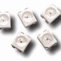
HSMx-A10x-xxxxx PLCC-2 Surface Mount LED Indicator Data Sheet Description This family of SMT LEDs is packaged in the industry standard PLCC-2 package. These SMT LEDs have high reliability performance and are designed to work under a wide range of environmental ...
Page 2
Package Dimensions 2.8 ± 0.2 2.2 ± 0.2 3.2 ± 0.2 CATHODE MARKING (ANODE MARKING FOR AlGaAs DEVICES) TOP MOUNT 2.8 ± 0.2 2.2 ± 0.2 3.2 ± 0.2 CATHODE MARKING REVERSE MOUNT NOTE: ALL DIMENSIONS IN MILLIMETERS. 2 1.9 ...
Page 3
Table 1. Device Selection Guide Red Part Number Min IV (mcd) HSMS-A100-J00J1 4.50 HSMS-A100-L00J1 11.20 HSMS-A100-H70J2 3.55 HSMS-A100-J80J2 5.60 HSMH-A100-L00J1 11.20 HSMH-A100-N00J1 28.50 HSMH-A100-M80J2 22.40 HSMC-A100-Q00J1 71.50 HSMC-A100-R00J1 112.50 HSMC-A101-S00J1 180.00 HSMZ-A100-T00J1 285.00 HSMC-A100-P30J1 45.00 Red Orange Part Number Min ...
Page 4
Yellow / Amber Part Number Min IV (mcd) HSMY-A100-J00J1 4.50 HSMY-A100-L00J1 11.20 HSMY-A100-J35J2 4.50 HSMA-A100-Q00J1 71.50 HSMA-A101-S00J1 180.00 HSMU-A100-S00J1 180.00 HSMA-A101-R8WJ1 140.00 HSMU-A100-S4WJ1 180.00 Yellow Green Part Number Min IV (mcd) HSMG-A100-J02J1 4.50 HSMG-A100-K72J2 9.00 HSME-A100-M02J1 18.00 HSME-A100-N82J1 35.50 Emerald ...
Page 5
Part Numbering System HSM Absolute Maximum Ratings (T = 25°C) A Parameters HSMS/D/Y/G [1] DC Forward Current 30 mA [2] ...
Page 6
... HSME-A100 AlInGaP Emerald HSMG-A100 GaP Green HSME-A100 AlInGaP Green HSMM-A10x InGaN Cyan HSMK-A10x InGaN Blue HSMB-A100 GaN HSMN-A10x InGaN Notes: 1. The dominant wavelength derived from the CIE Chromaticity Diagram and represents the color of the device the off-axis angle where the luminous intensity is 1/2 the peak intensity. ...
Page 7
BLUE 0.9 CYAN 0.8 GREEN 0.7 0.6 0.5 0.4 0.3 0.2 0.1 0 380 430 480 530 580 WAVELENGTH – nm 1.0 GaP EMERALD GREEN 0.8 GaP YELLOW GREEN 0.6 GaN BLUE 0.4 0.2 0 380 430 480 530 ...
Page 8
GaP/AlGaAs/ 0 AlInGaP -0.1 -0.2 InGaN/GaN -0.3 -100 - 100 150 TEMPERATURE – °C Figure 6. Forward voltage shift vs. temperature. 255 - 260 C 3 C/SEC. MAX. 217 C 200 C 150 ...
Page 9
TRAILER 200 mm MIN. FOR Ø 180 REEL. 200 mm MIN. FOR Ø 330 REEL. Figure 11. Tape leader and trailer dimensions. 4 ± 0.1 +0.1 Ø 1.5 –0 3.05 ± 0.1 Figure 12. Tape dimensions. 9 COMPONENT 480 mm ...
Page 10
LABEL AREA (111 mm) WITH DEPRESSION (0.25 mm) Figure 13. Reel dimensions. USER FEED DIRECTION PRINTED LABEL Figure 14. Reeling orientation 62.5 –2.5 ...
Page 11
Intensity Bin Select ( Individual reel will contain parts from one half bin only. X Min I Bin Full Distribution 2 2 half bins starting from ...
Page 12
Packaging Option ( Option Test Current Package Type Top Mount Top Mount Reverse Mount Reverse Mount Top Mount ...