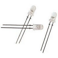
HLMP-ED57-LP000 Avago Technologies US Inc., HLMP-ED57-LP000 Datasheet

HLMP-ED57-LP000
Specifications of HLMP-ED57-LP000
Available stocks
Related parts for HLMP-ED57-LP000
HLMP-ED57-LP000 Summary of contents
Page 1
... HLMP-EL55/EG55/EL57/EH57/ED57 3 T mm) Precision Optical Performance AlInGaP 4 LED Lamps Data Sheet Description These Precision Optical Performance AlInGaP Leds pro- vide superior light output for excellent readability in sun- light and are extremely reliable. AlInGaP Led technology provides extremely stable light output over long periods of time. Precision Optical Performance lamps utilize the aluminum indium gallium phosphide (AlInGaP) technol- ogy. These Led lamps are tinted, diffused, T-1 incorporating second generation optics producing well defined radiation patterns at specific viewing cone an- gles. There are two families of amber, red, and red-orange lamps ...
Page 2
... Part Numbering System HLMP - Device Selection Guide for AlInGaP Color and Dominant Wavelength ld (nm) Typ. Part Number HLMP-eL55-GK0dd Amber 590 HLMP-eL55-GHKdd Amber 590 HLMP-eL55-HJKxx Amber 590 HLMP-eL55-JKLdd Amber 590 HLMP-eL55-LP000 Amber 590 HLMP-eG55-GK0dd Red 626 HLMP-eG55-HJ0xx Red 626 HLMP-eG55-JK0xx Red 626 Device Selection Guide for AlInGaPII Color and Dominant Wavelength ld (nm) Typ ...
Page 3
Package Dimensions 5.00 ± 0.20 (0.197 ± 0.008) 8.71 ± 0.20 (0.045 ± 0.008) (0.343 ± 0.008 31.60 (1.244) MIN. 0.70 (0.028) MAX. CATHODE LEAD 1.00 MIN. (0.020 ± 0.004) (0.039) (0.228 ± 0.008) CATHODE FLAT 2.54 ± 0.38 (0.100 ...
Page 4
Absolute Maximum Ratings 25°C A [1,2,3] dC Forward Current . ...................................................................................................... 50 mA [2,3] Peak Pulsed Forward Current . ........................................................................................100 mA Average Forward Current [3] . ................................................................................................... 30 mA Reverse Voltage (I = 100 µA) . ......................................................................................................... Led Junction Temperature . ........................................................................................................ 130°C Operating Temperature ..........................................................................................–40°C to +100°C Storage Temperature ...............................................................................................–40°C to +100°C Notes: 1. derate linearly as shown in Figure 4. 2. For long term performance with minimal light output degradation, drive currents between 10 mA and 30 mA are recommended. For more information on recommended drive conditions, please refer to Application Brief I-024 (5966-3087e). 3. Please contact your Avago Technologies sales representative about operating currents below 10 mA. Electrical/Optical ...
Page 5
AMBER 0.5 0 500 550 600 WAVELENGTH – nm Figure 1. Relative intensity vs. peak wavelength. 100 RED 50 40 AMBER 1.0 1.5 2.0 2.5 3.0 V – FORWARD VOLTAGE – ...
Page 6
Intensity Bin Limits (mcd at 20 mA) Bin Name Min. Max. G 140 180 H 180 240 J 240 310 K 310 400 L 400 520 M 520 680 N 680 880 P 880 1150 Tolerance for each bin limit is ± 15%. 6 Amber Color ...
Page 7
Precautions: Lead Forming: • The leads of an Led lamp may be preformed or cut to length prior to insertion and soldering on PC board. • For better control recommended to use proper tool to precisely form and cut the leads to applicable length rather than doing it manually. • If manual lead cutting is necessary, cut the leads after the soldering process. The solder connection forms a mechanical ground which prevents mechanical stress due to lead cutting from traveling into Led package. This is highly recommended for hand solder opera- tion, as the excess lead length also acts as small heat sink. Soldering and Handling: • Care must be taken during PCB assembly and soldering process to prevent damage to the Led component. • ...
Page 8
Refer to application note AN5334 for more information about soldering and handling of high brightness TH Led lamps. Example of Wave Soldering Temperature Profile for TH LED TURBULENT WAVE 250 200 150 100 50 PREHEAT Ammo Pack Drawing 6.35 ± 1.30 (0.25 ± 0.0512) 9.125 ± 0.625 (0.3593 ± 0.0246) 18.00 ± 0.50 ...
Page 9
Packaging Box for Ammo Packs FROM LEFT SIDE OF BOX, ADHESIVE TAPE MUST BE FACING UPWARD. ANODE LEAD LEAVES THE BOX FIRST. NOTE: THE DIMENSION FOR AMMO PACK IS APPLICABLE FOR THE DEVICE WITH STANDOFF AND WITHOUT STANDOFF. Packaging Label: ...
Page 10
Avago Baby Label (Only available on bulk packaging) Lamps Baby Label (1P) PART #: Part Number (1T) LOT #: Lot Number (9D)MFG DATE: Manufacturing Date C/O: Country of Origin Customer P/N: Supplier Code: Acronyms and Definition: BIN: (i) Color bin only or VF bin only (Applicable ...


