ASMT-MWH2-NFH00 Avago Technologies US Inc., ASMT-MWH2-NFH00 Datasheet
ASMT-MWH2-NFH00
Specifications of ASMT-MWH2-NFH00


Related parts for ASMT-MWH2-NFH00


ASMT-MWH2-NFH00 Summary of contents
Page 1
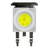
... ASMT-Mx6x TM Moonstone ½W Power LED Light Source Data Sheet Description ½W Power LED Light Source is a high performance energy efficient device which can handle high thermal and high driving current. The exposed pad design has excellent heat transfer from the package to the motherboard. ...
Page 2
... Unless otherwise stated, the tolerance for dimension is ±0.1mm. Device Selection Guide (Tj = 25°C) Part Number Color ASMT-MW62-NGJ00 Cool White ASMT-MW62-NHK00 ASMT-MY62-NGJ00 Warm White Notes: 1. ΦV is the total luminous flux output as measured with an integrating sphere at 25ms mono pulse condition. 2. Flux tolerance is ± ...
Page 3
... Part Numbering System ASMT – – Packaging Option 0 – Tube 1 – Tape and Reel Color Bin Selection Maximum Flux Bin Minimum Flux Bin Heat Sink 2 – Electrically Isolated Silicone Type 6 – Non-diffused Color W – Cool White Y – Warm White Absolute Maximum Ratings 25° ...
Page 4
WAVELENGTH - nm Figure 1. Relative Intensity vs. Wavelength 1.4 1.3 1.2 1.1 1 0.9 0.8 0.7 0.6 0.5 0.4 0.3 0.2 0.1 0 ...
Page 5
Rθ =140°C/W 90 J-A Rθ =120°C/W J-A Rθ =100°C/W J 100 AMBIENT TEMPERATURE, T Figure 7. Maximum forward current vs. ambient temperature. Derated based 145°C, Rθ ...
Page 6
Color bin selection [ Individual reel or tube will contain LEDs from one color bin only. Cool White Selection Bin 0 Full Distribution A A only B B only C C only D D only E E only ...
Page 7
Primary Color Binning Cool White Color Limits (Chromaticity Coordinates) Bin A X 0.367 0.362 Y 0.400 0.372 Bin B X 0.362 0.356 Y 0.372 0.330 Bin C X 0.329 0.329 Y 0.369 0.345 Bin D X 0.329 0.329 Y 0.345 ...
Page 8
Sub-Color Binning (Only Applicable for Color Bin A to Bin D and Bin G to Bin H) Color Limits Cool White Color Limits (Chromaticity Coordinates) Bin A1 X 0.364 0.367 Y 0.383 0.400 Bin A2 X 0.364 0.362 Y 0.383 ...
Page 9
Package Tube – Option 0 1.00 5.80 4.65 5.50 37.00 5.45 10.10 8.30 TOP VIEW Figure 13. Tube dimensions Tape & Reel – Option SECTION B Figure 14. Carrier tape dimensions 9 535.00 FRONT VIEW A B ...
Page 10
END MINIMUM OF 160 mm MOUNTED WITH OF EMPTY COMPONENT COMPONENTS POCKETS SEALED WITH COVER TAPE. *Note: Tape & Reel Packaging only applicable as per this datasheet only. Figure 15. Carrier tape leader and trailer dimensions Reel Dimension Figure 16. ...
Page 11
Handling Precaution The encapsulation material of the product is made of sili- cone for better reliability of the product. As silicone is a soft material, please do not press on the silicone or poke a sharp object onto the silicone. ...