3214W-1-202E Bourns Inc., 3214W-1-202E Datasheet
3214W-1-202E
Manufacturer Part Number
3214W-1-202E
Description
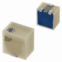
TRIMPOT 2K OHM 4MM TOP ADJ SMD
Manufacturer
Bourns Inc.
Series
3214 - Sealedr
Specifications of 3214W-1-202E
Tolerance
±10%
Number Of Turns
5
Temperature Coefficient
±100ppm/°C
Resistance (ohms)
2K
Power (watts)
0.25W, 1/4W
Adjustment Type
Top Adjustment
Mounting Type
Surface Mount
Resistive Material
Cermet
Package / Case
Square - 0.200" L x 0.190" W x 0.200" H (5.10mm x 4.80mm x 5.10mm)
Resistance In Ohms
2.00K
Resistance
2 KOhms
Power Rating
0.25 Watt (1/4 Watt)
Operating Temperature Range
- 65 C to + 150 C
Element Type
Cermet
Dimensions
4.8 mm W x 5.1 mm L
Product
Trimmers
Termination Style
SMD/SMT
Voltage Rating
300 Volts
Taper
Linear
Angle, Mechanical
Wiper idles
Dielectric Strength
600 V
Insulation Resistance
500 VDC @100 megaohms (Min)
Load Life
1000 hr @ 0.5 W, +85 °C
Material, Element
Cermet
Power, Rating
0.25 W
Resistance, Insulation
100 Megohms
Resolution
Infinite
Rotational Life
200 Cycles
Temperature, Operating, Maximum
+150 °C
Temperature, Operating, Minimum
-65 °C
Termination
SMT
Torque
180 g-cm
Weight
0.02 Oz.
Track Resistance
2kohm
No. Of Turns
5
Resistance Tolerance
± 10%
Potentiometer Mounting
SMD
Termination Type
SMD
Resistance Min
20ohm
Rohs Compliant
Yes
Filter Terminals
SMD
Lead Free Status / RoHS Status
Lead free / RoHS Compliant
Lead Free Status / RoHS Status
Lead free / RoHS Compliant, Lead free / RoHS Compliant
Other names
3214W-202ETR
Available stocks
Company
Part Number
Manufacturer
Quantity
Price
Company:

Part Number:
3214W-1-202E
Manufacturer:
BOURNS
Quantity:
1 000


Electrical Characteristics
Standard Resistance Range
Resistance Tolerance ............... ±10 % std.
Absolute Minimum Resistance
Contact Resistance Variation
Resolution ..................... Essentially Infi nite
Insulation Resistance ................... 500 vdc.
Dielectric Strength
Adjustment Angle ...................5 turns nom.
Environmental Characteristics
Power Rating (300 volts max.)
Temperature Range ....... -65 °C to +150 °C
Temperature Coeffi cient ....... ±100 ppm/°C
Humidity ........... MIL-STD 202 Method 106
Vibration ..........20 G TRS±1 %; VRS ±1 %
Shock ............100 G TRS ±1 %; VRS±1 %
Load Life
Rotational Cycling .....................200 cycles
Thermal Shock ..............................5 cycles
Physical Characteristics
Mechanical Stop ...................... Wiper idles
Torque .................................180 g-cm max.
Weight ................... Approximately 0.01 oz.
Marking ..................... Manufacturer’s code,
Solderability ...................Per MIL-STD-202,
Wiper ................... 50 % (Actual TR) ±10 %
Flammability .................................. UL94V0
Pushover Strength
Adjustment Tool ..................................H-91
Model
Style
Standard or Modifi ed
Product Indicator
Resistance Code
Embossed Tape Designator
Consult factory for other available options.
† -2 has a treated stainless steel shaft
How To Order
Sea Level .................. 600 vac (1 minute)
85 °C ........................................ 0.25 watt
150 °C ........................................... 0 watt
J, G ............................................. 4.4 lbs.
W, X .................................................. 1 lb.
-1 = IR Refl ow (standard)
†-2 = Wave Solderable
-FW5 = .070” ± .010” Shaft Extension
E = Style J, G: 500 pcs./7 ” reel (standard)
G = Style J, G: 1500 pcs./13 ” reel (standard)
G = Style J, G: 1500 pcs./13 ” reel (FW5)
..........................10 ohms to 2 megohms
..................................... 1 % or 2.0 ohms
............................... 3 % or 3 ohms max.
...........@ 85 °C rated power 1,000 hours
Style W: 250 pcs./7 ” reel (standard)
Style X: 200 pcs./7 ” reel (standard)
Style W: 1000 pcs./13 ” reel (standard)
Style X: 850 pcs./13 ” reel (standard)
Style W, X: 600 pcs./13 ” reel (FW5)
resistance code and date code
(see standard resistance table)
TRS ±2 %; IR 10 megohms
TRS ±2 %; VRS ±1 %
3214 J - 1 - 502 E
(whichever is greater)
(whichever is greater)
(whichever is greater)
TRS 3 ohms or 3 %
TRS 3 ohms or 3 %
100 megohms min.
Method 208
(.060)
Features
■
■
■
■
(.079)
3214W Top Adjust
3214 - 5-Turn Trimpot
3214J Side Adjust
(.061)
(.100)
1.5
(.050)
ADJUSTMENT SLOT
2.0
1.6
1.3
(.155)
2.5
X
ADJUSTMENT SLOT
Product Dimensions
3.9
Surface Mount 4 mm Square / Multiturn
Cermet / Industrial / Sealed
Halogen free** with date code 114
Sealed to withstand board wash
processing
Pick and place centering design, with fl ush
adjustment
X
“halogen free” if (a) the Bromine (Br ) content is 900 ppm or less; (b) the Chlorine ( Cl ) content is 900 ppm or less;
(.079)
3
1
(.020)
(.022)
(.079)
3 PLCS
2.0
3 PLCS.
0.5
(.020)
(.022)
DIA.
0.6
2 PLCS.
2.0
0.5
(.102)
0.6
(.102)
2.6
2.6
**Bourns follows the prevailing defi nition of “halogen free” in the industry. Bourns considers a product to be
(.157)
WIDE
DEEP
4.0
WIDE
DEEP
(.050)
1.3
(.090)
(.114)
2.3
2.9
(.139)
(.100)
2 PLCS.
3.5
(.047)
2.5
1.2
(.095)
(.047)
(.060)
1.2
2.4
1.5
2
(.045)
1.14
DIA.
(.020)
(.007)
2
0.5
0.2
(.050)
1.3
(.028)
(.195)
(.180)
(.032)
0.7
(.200)
(.040)
5.0
4.6
0.8
(.208)
5.1
1.0
5.3
Customers should verify actual device performance in their specifi c applications.
(.007)
and (c) the total Bromine (Br) and Chlorine ( Cl ) content is 1500 ppm or less.
(.032)
2 PLCS.
3 PLCS.
0.2
(.034)
0.8
0.9
.008
1
0.2
3
(.032)
2 PLCS.
®
0.8
2 PLCS.
(.039)
(.190)
(.190)
(.146)
(.090)
(.050)
3.71
1.0
4.8
4.8
2.3
1.3
Trimming Potentiometer
*RoHS Directive 2002/95/EC Jan 27, 2003 including Annex.
■
■
■
3214G Side Adjust
(.032)
3214X Top Adjust
(.060)
ADJUSTMENT SLOT
0.8
(.050)
1.5
X
(.050)
4 mm design meets EIA/EIAJ/IPC/VECI
SMD standard trimmer footprint
RoHS compliant* - see
information
trimmers
For trimmer applications/processing
guidelines,
1.3
1.3
(.100)
(.020)
(.022)
ADJUSTMENT SLOT
1
2.5
Specifi cations are subject to change without notice.
.0.5
X
(.079)
0.6
2 PLCS
DIA.
2.0
2 PLCS.
3 PLCS.
(.020)
(.022)
(.108)
0.5
2.7
0.6
WIDE
DEEP
(.075)
2 PLCS.
(.050)
1.9
(.205)
1.3
DIMENSIONS:
5.2
WIDE
DEEP
click here
on lead free surface mount
TYP.
(.139)
3.5
(.090)
(.047)
2.3
(.095)
1.2
(.200)
2.4
(.050)
2
5.1
(.079)
1.3
(.047)
(.155)
2.0
1.2
3.9
2
(INCHES)
processing
(.020)
MM
(.005)
0.13
0.5
(.050)
1.3
(.200)
(.040)
5.1
1.0
(.208)
(.008)
5.3
(.236)
(.180)
0.2
6.0
4.6
3 PLCS.
(.032)
0.8
(.007)
1
0.2
3
2 PLCS.
2 PLCS.
(.02)
(.034)
0.5
(.090)
0.9
2.3
(.190)
(.225)
(.100)
(.152)
4.8
5.7
2.5
3.9
(.190)
TYP.
4.8
Related parts for 3214W-1-202E
Image
Part Number
Description
Manufacturer
Datasheet
Request
R

Part Number:
Description:
POT, TRIM, 500KOHM, 5TURN, 10%, SMD
Manufacturer:
Bourns Inc.
Datasheet:
Part Number:
Description:
TRIMPOT 1K OHM 4MM TOP ADJ SMD
Manufacturer:
Bourns Inc.
Datasheet:
Part Number:
Description:
TRIMPOT 10K OHM 4MM TOP ADJ SMD
Manufacturer:
Bourns Inc.
Datasheet:
Part Number:
Description:
TRIMPOT 100K OHM 4MM TOP ADJ SMD
Manufacturer:
Bourns Inc.
Datasheet:
Part Number:
Description:
TRIMPOT 5K OHM 4MM TOP ADJ SMD
Manufacturer:
Bourns Inc.
Datasheet:
Part Number:
Description:
TRIMPOT 50K OHM 4MM TOP ADJ SMD
Manufacturer:
Bourns Inc.
Datasheet:
Part Number:
Description:
TRIMPOT 1M OHM 4MM CERMET SMD
Manufacturer:
Bourns Inc.
Datasheet:
Part Number:
Description:
TRIMPOT 200K OHM 4MM CERMET SMD
Manufacturer:
Bourns Inc.
Datasheet:
Part Number:
Description:
TRIMPOT 2M OHM 4MM CERMET SMD
Manufacturer:
Bourns Inc.
Datasheet:

Part Number:
Description:
TRIMPOT 10 OHM 4MM CERMET SMD
Manufacturer:
Bourns Inc.
Datasheet:
Part Number:
Description:
POT, TRIMMER, 50OHM, 5 TURN, SMD
Manufacturer:
Bourns Inc.
Datasheet:
Part Number:
Description:
TRIMPOT 20K OHM 4MM TOP ADJ SMD
Manufacturer:
Bourns Inc.
Datasheet:
Part Number:
Description:
TRIMPOT 200 OHM 4MM TOP ADJ SMD
Manufacturer:
Bourns Inc.
Datasheet:
Part Number:
Description:
TRIMPOT 500 OHM 4MM TOP ADJ SMD
Manufacturer:
Bourns Inc.
Datasheet:
Part Number:
Description:
TRIMPOT 100 OHM 4MM TOP ADJ SMD
Manufacturer:
Bourns Inc.
Datasheet:
3214W-1-202E Summary of contents
Page 1
... PLCS. 2.0 (.079) 2.3 1.3 0.9 (.090) (.050) (.034) 1.3 2 PLCS. 0.5 (.050) 2 PLCS. (.020) 0.2 (.007) 3214W Top Adjust 3.9 (.155) 1.3 5.1 3.5 (.050) 1 (.200) (.139) 1.2 (.047) 4.8 2.5 (.190) (.100) 2 1.5 DIA. 3 2.6 ( ...
Page 2
Packaging Specifi cations J & G Styles .04 MAX. (.002) 4.5 MAX. (.177) 5.52 ± .05 (.217 ± .002) 5.55 ± .10 (J) 1.5 + .10/ –.00 (.219 ± .004) DIA. (.059 + .004/ –.000) 6.25 ± .10 ...