3214W-1-202E Bourns Inc., 3214W-1-202E Datasheet
3214W-1-202E
Manufacturer Part Number
3214W-1-202E
Description
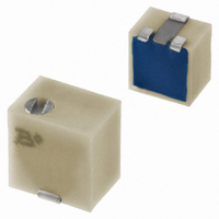
TRIMPOT 2K OHM 4MM TOP ADJ SMD
Manufacturer
Bourns Inc.
Series
3214 - Sealedr
Specifications of 3214W-1-202E
Tolerance
±10%
Number Of Turns
5
Temperature Coefficient
±100ppm/°C
Resistance (ohms)
2K
Power (watts)
0.25W, 1/4W
Adjustment Type
Top Adjustment
Mounting Type
Surface Mount
Resistive Material
Cermet
Package / Case
Square - 0.200" L x 0.190" W x 0.200" H (5.10mm x 4.80mm x 5.10mm)
Resistance In Ohms
2.00K
Resistance
2 KOhms
Power Rating
0.25 Watt (1/4 Watt)
Operating Temperature Range
- 65 C to + 150 C
Element Type
Cermet
Dimensions
4.8 mm W x 5.1 mm L
Product
Trimmers
Termination Style
SMD/SMT
Voltage Rating
300 Volts
Taper
Linear
Angle, Mechanical
Wiper idles
Dielectric Strength
600 V
Insulation Resistance
500 VDC @100 megaohms (Min)
Load Life
1000 hr @ 0.5 W, +85 °C
Material, Element
Cermet
Power, Rating
0.25 W
Resistance, Insulation
100 Megohms
Resolution
Infinite
Rotational Life
200 Cycles
Temperature, Operating, Maximum
+150 °C
Temperature, Operating, Minimum
-65 °C
Termination
SMT
Torque
180 g-cm
Weight
0.02 Oz.
Track Resistance
2kohm
No. Of Turns
5
Resistance Tolerance
± 10%
Potentiometer Mounting
SMD
Termination Type
SMD
Resistance Min
20ohm
Rohs Compliant
Yes
Filter Terminals
SMD
Lead Free Status / RoHS Status
Lead free / RoHS Compliant
Lead Free Status / RoHS Status
Lead free / RoHS Compliant, Lead free / RoHS Compliant
Other names
3214W-202ETR
Available stocks
Company
Part Number
Manufacturer
Quantity
Price
Company:

Part Number:
3214W-1-202E
Manufacturer:
BOURNS
Quantity:
1 000


Standard Resistance Range
Resistance Tolerance ................±10 % std.
Absolute Minimum Resistance
Contact Resistance Variation
Resolution.......................Essentially Infinite
Insulation Resistance ....................500 vdc.
Dielectric Strength
Adjustment Angle....................5 turns nom.
Power Rating (300 volts max.)
Temperature Range ........-65 °C to +150 °C
Temperature Coefficient ........±100 ppm/°C
Humidity ............MIL-STD 202 Method 106
Vibration ...........20 G TRS±1 %; VRS ±1 %
Shock .............100 G TRS ±1 %; VRS±1 %
Load Life
Rotational Cycling......................200 cycles
Thermal Shock ...............................5 cycles
Mechanical Stop .......................Wiper idles
Torque .................................180 g-cm max.
Weight ....................Approximately 0.01 oz.
Marking .....................Manufacturer’s code,
Solderability ..................Per MIL-STD-202,
Wiper....................50 % (Actual TR) ±10 %
Flammability ..................................UL94V0
Pushover Strength
Adjustment Tool ..................................H-91
Model
Style
Standard or Modified
Product Indicator
Resistance Code
Embossed Tape Designator
Consult factory for other available options.
† -2 has a treated stainless steel shaft
How To Order
Electrical Characteristics
........................................1 % or 2.0 ohms
..................................3 % or 3 ohms max.
Sea Level .....................600 vac (1 minute)
Environmental Characteristics
85 °C ..........................................0.25 watt
150 °C .............................................0 watt
TRS 3 ohms or 3 % (whichever is greater)
TRS 3 ohms or 3 % (whichever is greater)
Physical Characteristics
J, G ................................................4.4 lbs.
W, X ..............................................2.2 lbs.
G = Style J, G: 1500 pcs./13 ” reel (standard)
G = Style J, G: 1500 pcs./13 ” reel (FW5)
........................................10 to 2 megohm
.............@ 85 °C rated power 1,000 hours
-FW5 = .070” ± .010” Shaft Extension
E = Style J, G: 500 pcs./7 ” reel (standard)
†
-1 = IR Reflow (standard)
-2 = Wave Solderable
Style W: 250 pcs./7 ” reel (standard)
Style X: 200 pcs./7 ” reel (standard)
Style W: 1000 pcs./13 ” reel (standard)
Style X: 850 pcs./13 ” reel (standard)
Style W, X: 600 pcs./13 ” reel (FW5)
resistance code and date code
(see standard resistance table)
TRS ±2 %; IR 10 megohms
3214 J - 1 - 502 E
TRS ±2 %; VRS ±1 %
(whichever is greater)
100 megohms min.
Method 208
3214 - 5-Turn Trimming Potentiometer
Features
3214W Top Adjust
(.061)
(.060)
(.079)
(.100)
3214J Side Adjust
1.5
(.050)
1.6
ADJUSTMENT SLOT
(.155)
2.5
2.0
1.3
ADJUSTMENT SLOT
Surface Mount 4 mm Square / Multiturn
X
3.9
Cermet / Industrial / Sealed
Sealed to withstand board wash
processing
Pick and place centering design, with
flush adjustment
X
3
1
(.079)
(.020)
(.079)
(.022)
3 PLCS.
(.020)
2.0
(.022)
3 PLCS
0.5
2.0
DIA.
0.6
2 PLCS.
0.5
0.6
(.102)
(.102)
2.6
2.6
(.157)
WIDE
DEEP
4.0
WIDE
DEEP
(.050)
1.3
(.114)
(.090)
2.9
2.3
(.139)
(.100)
2 PLCS.
3.5
2.5
(.047)
(.047)
1.2
(.060)
(.095)
1.2
1.5
2
2.4
(.045)
1.14
DIA.
(.020)
(.007)
2
0.5
0.2
(.050)
1.3
(.028)
(.032)
0.7
(.180)
(.195)
(.200)
(.040)
0.8
(.208)
5.0
4.6
5.1
1.0
5.3
Customers should verify actual device performance in their specific applications.
(.007)
(.032)
3 PLCS.
2 PLCS.
0.2
(.034)
0.8
.008
0.9
0.2
1
3
2 PLCS.
(.032)
0.8
2 PLCS.
(.190)
(.039)
(.190)
(.050)
(.146)
(.090)
4.8
3.71
1.0
1.3
4.8
2.3
*RoHS Directive 2002/95/EC Jan 27 2003 including Annex.
(.032)
3214X Top Adjust
3214G Side Adjust
ADJUSTMENT SLOT
(.060)
0.8
(.050)
X
1.5
(.050)
1.3
(.100)
4 mm design meets EIA/EIAJ/IPC/VECI
SMD standard trimmer footprint
Patent #5047746 advanced drive/wiper
mechanism
RoHS compliant* - see
information
trimmers
1.3
(.020)
(.022)
1
2.5
ADJUSTMENT SLOT
.0.5
0.6
Specifications are subject to change without notice.
2 PLCS
X
(.079)
2.0
2 PLCS.
DIA.
3 PLCS.
(.020)
(.022)
(.108)
0.5
2.7
0.6
WIDE
DEEP
(.075)
2 PLCS.
1.9
(.050)
(.205)
1.3
5.2
WIDE
DEEP
TYP.
on lead free surface mount
(.139)
3.5
(.090)
(.047)
(.095)
2.3
1.2
(.200)
2.4
(.050)
2
5.1
(.079)
1.3
(.047)
(.155)
2.0
1.2
3.9
2
processing
(.005)
(.020)
0.13
(.050)
0.5
(.200)
(.040)
1.3
5.1
1.0
(.208)
(.008)
5.3
0.2
(.236)
(.180)
6.0
4.6
3 PLCS.
(.032)
0.8
(.007)
1
0.2
3
2 PLCS.
2 PLCS.
(.02)
(.034)
0.5
(.090)
0.9
(.190)
(.225)
2.3
(.100)
(.152)
4.8
5.7
2.5
3.9
(.190)
TYP.
4.8
Related parts for 3214W-1-202E
Image
Part Number
Description
Manufacturer
Datasheet
Request
R

Part Number:
Description:
POT, TRIM, 500KOHM, 5TURN, 10%, SMD
Manufacturer:
Bourns Inc.
Datasheet:
Part Number:
Description:
TRIMPOT 1K OHM 4MM TOP ADJ SMD
Manufacturer:
Bourns Inc.
Datasheet:
Part Number:
Description:
TRIMPOT 10K OHM 4MM TOP ADJ SMD
Manufacturer:
Bourns Inc.
Datasheet:
Part Number:
Description:
TRIMPOT 100K OHM 4MM TOP ADJ SMD
Manufacturer:
Bourns Inc.
Datasheet:
Part Number:
Description:
TRIMPOT 5K OHM 4MM TOP ADJ SMD
Manufacturer:
Bourns Inc.
Datasheet:
Part Number:
Description:
TRIMPOT 50K OHM 4MM TOP ADJ SMD
Manufacturer:
Bourns Inc.
Datasheet:
Part Number:
Description:
TRIMPOT 1M OHM 4MM CERMET SMD
Manufacturer:
Bourns Inc.
Datasheet:
Part Number:
Description:
TRIMPOT 200K OHM 4MM CERMET SMD
Manufacturer:
Bourns Inc.
Datasheet:
Part Number:
Description:
TRIMPOT 2M OHM 4MM CERMET SMD
Manufacturer:
Bourns Inc.
Datasheet:

Part Number:
Description:
TRIMPOT 10 OHM 4MM CERMET SMD
Manufacturer:
Bourns Inc.
Datasheet:
Part Number:
Description:
POT, TRIMMER, 50OHM, 5 TURN, SMD
Manufacturer:
Bourns Inc.
Datasheet:
Part Number:
Description:
TRIMPOT 20K OHM 4MM TOP ADJ SMD
Manufacturer:
Bourns Inc.
Datasheet:
Part Number:
Description:
TRIMPOT 200 OHM 4MM TOP ADJ SMD
Manufacturer:
Bourns Inc.
Datasheet:
Part Number:
Description:
TRIMPOT 500 OHM 4MM TOP ADJ SMD
Manufacturer:
Bourns Inc.
Datasheet:
Part Number:
Description:
TRIMPOT 100 OHM 4MM TOP ADJ SMD
Manufacturer:
Bourns Inc.
Datasheet:
3214W-1-202E Summary of contents
Page 1
... PLCS. 2.0 (.079) 2.3 1.3 0.9 (.090) (.050) (.034) 1.3 2 PLCS. 0.5 (.050) 2 PLCS. (.020) 0.2 (.007) 3214W Top Adjust 3.9 (.155) 1.3 3.5 5.1 (.050) 1 (.200) (.139) 1.2 (.047) 4.8 2.5 (.190) (.100) 2 1.5 DIA. 3 2.6 ( ...
Page 2
Packaging Specifications J & G Styles .04 MAX. (.002) 4.5 MAX. (.177) 5.52 ± .05 (.217 ± .002) 5.56 ± .10 (J) 1.5 + .10/ –.00 (.219 ± .004) DIA. (.059 + .004/ –.000) 6.25 ± .10 (G) ...