LTM4618EV#PBF Linear Technology, LTM4618EV#PBF Datasheet - Page 7
LTM4618EV#PBF
Manufacturer Part Number
LTM4618EV#PBF
Description
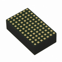
IC DC-DC UMODULE BUCK 6A 84-LGA
Manufacturer
Linear Technology
Series
µModuler
Type
Point of Load (POL) Non-Isolatedr
Datasheet
1.LTM4618EVPBF.pdf
(24 pages)
Specifications of LTM4618EV#PBF
Output
0.8 ~ 5 V
Number Of Outputs
1
Power (watts)
30W
Mounting Type
Surface Mount
Voltage - Input
4.5 ~ 26.5 V
Package / Case
84-LGA
1st Output
0.8 ~ 5 VDC @ 6A
Size / Dimension
0.59" L x 0.35" W x 0.17" H (15mm x 9mm x 4.32mm)
Power (watts) - Rated
30W
Operating Temperature
-40°C ~ 125°C
Lead Free Status / RoHS Status
Lead free / RoHS Compliant
3rd Output
-
2nd Output
-
Available stocks
Company
Part Number
Manufacturer
Quantity
Price


PIN FUNCTIONS
NC (A1): No Connect. Leave fl oating.
FREQ (A2): Frequency Selection Pin. An internal low pass
fi lter is tied to this pin. The frequency can be selected with
a voltage from this pin to SGND. A programming resistor
divider can be used to set the operating frequency. The
suggested operating frequency range is 400kHz to 780kHz.
Operating frequencies as low as 250kHz are possible af-
ter evaluating the inductor ripple current for the desired
confi guration. See the Applications Information section.
MODE/PLLIN (A3): Mode Selection or External Synchroni-
zation Pin. Tying this pin to INTV
operation. Tying this pin low enables forced continuous
mode operation. Burst Mode operation is enabled by fl oat-
ing the pin. A clock on the pin will force the controller into
forced continuous mode of operation and synchronize to
the internal oscillator. The programming DC voltage has
to be removed for clock synchronization.
PGND (BANK 2: A4, B4, D4-D7, E1-E7, F1-F7, G1-G7,
H1-H7, J5-J7, K5, K7, L5-L7, M5-M7): Power ground
pins for both input and output returns.
V
Apply input voltage between these pins and PGND pins.
Recommend placing input decoupling capacitance directly
between V
TK/SS (B1): Output Voltage Tracking and Soft-Start Pin. An
internal soft-start current of 1.3μA charges the soft-start
capacitor. See the Applications Information section.
RUN (B2): Run Control Pin. A voltage above 1.35V on
IN
(BANK 1: A5-A7, B5-B7, C5-C7): Power Input Pins.
IN
pins and PGND pins.
SGND/PGND
CC
BANK 1
CNTRL
enables pulse-skipping
V
IN
7
6
5
4
3
2
1
A
B
C
D
E
F
G
this pin turns on the module. Forcing this pin below 1.1V
will shut down the output. The RUN pin has a 1μA pull-
up current source that increases to 10μA as the RUN pin
voltage reaches 1.5V and up to compliance. Therefore the
pin can be left fl oating for normal operation. A maximum
of 6V can be applied to the pin. A voltage divider can be
used for a UVLO function. See the Applications Informa-
tion section.
SGND (B3, C2 and C3): Signal Ground Pin. Return ground
path for all analog and low power circuitry. Tie a single
connection to PGND. See applications for details.
COMP (C1): Current control threshold and error ampli-
fi er compensation point. The module has been internally
compensated for most I/O ranges.
EXTV
INTV
drivers. If a 5V source is available, the internal LDO is
disabled, and the power dissipation is lower, especially at
higher input voltages. See the Applications Information
section.
V
nally, this pin is connected to V
resistor. Different output voltages can be programmed
with an additional resistor between V
See applications for details.
PGOOD (D2): Output Voltage Power Good Indicator. Open-
drain logic output that is pulled to ground when the output
voltage is not within ±7.5% of the regulation point.
INTV
FB
H
(D1): The negative input of the error amplifi er. Inter-
CC
CC
CC
J
LDO and powers the internal circuitry and MOSFET
(D3): Internal 5V Regulator Output. This pin is for
(C4): External Voltage Input. Bypasses the internal
K
L
M
BANK 2
PGND
BANK 3
V
OUT
SW
OUT
with a 60.4kΩ precision
FB
LTM4618
and SGND pins.
4618fa
7
Related parts for LTM4618EV#PBF
Image
Part Number
Description
Manufacturer
Datasheet
Request
R

Part Number:
Description:
6a Dc/dc
Manufacturer:
Linear Technology Corporation
Datasheet:

Part Number:
Description:
BOARD DEMO LTM4618
Manufacturer:
Linear Technology
Datasheet:
Part Number:
Description:
CD ROM LINEARVIEW DATASHEETS
Manufacturer:
Linear Technology
Part Number:
Description:
Standalone Linear Li-Ion Battery Charger with Thermal Regulation in ThinSOT
Manufacturer:
Linear Technology Corporation
Datasheet:
Part Number:
Description:
Low noise, high frequency, 8th order linear phase lowpass filter
Manufacturer:
Linear Technology Corporation
Datasheet:
Part Number:
Description:
Manufacturer:
Linear Technology Corporation
Datasheet:
Part Number:
Description:
Manufacturer:
Linear Technology Corporation
Datasheet:
Part Number:
Description:
Manufacturer:
Linear Technology Corporation
Datasheet:
Part Number:
Description:
Manufacturer:
Linear Technology Corporation
Datasheet:
Part Number:
Description:
Manufacturer:
Linear Technology Corporation
Datasheet:
Part Number:
Description:
Manufacturer:
Linear Technology Corporation
Datasheet:
Part Number:
Description:
Manufacturer:
Linear Technology Corporation
Datasheet:
Part Number:
Description:
Dual and Quad, JFET Input Precision High Speed Op Amps
Manufacturer:
Linear Technology Corporation
Datasheet:
Part Number:
Description:
Manufacturer:
Linear Technology Corporation
Datasheet:
Part Number:
Description:
1, 2, 6 and 8 Channel, 10-Bit Serial I/O Data Acquisition Systems
Manufacturer:
Linear Technology Corporation
Datasheet: