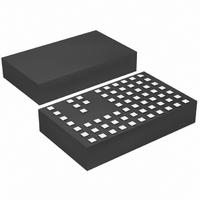
LTM4604IV#PBF Linear Technology, LTM4604IV#PBF Datasheet - Page 10

LTM4604IV#PBF
Manufacturer Part Number
LTM4604IV#PBF
Description
IC DC/DC UMODULE 4A 66-LGA
Manufacturer
Linear Technology
Series
µModuler
Type
Point of Load (POL) Non-Isolatedr
Datasheet
1.LTM4604EVPBF.pdf
(20 pages)
Specifications of LTM4604IV#PBF
Design Resources
LTM4604 Spice Model
Output
0.8 ~ 5 V
Number Of Outputs
1
Power (watts)
20W
Mounting Type
Surface Mount
Voltage - Input
2.38 ~ 5.5 V
Package / Case
66-LGA
1st Output
0.8 ~ 5 VDC @ 4A
Size / Dimension
0.59" L x 0.35" W x 0.09" H (15mm x 9mm x 2.3mm)
Power (watts) - Rated
20W
Operating Temperature
-40°C ~ 85°C
Lead Free Status / RoHS Status
Lead free / RoHS Compliant
3rd Output
-
2nd Output
-
Available stocks
Company
Part Number
Manufacturer
Quantity
Price
LTM4604
Run Enable and Soft-Start
The RUN/SS pin provides dual functions of enable and
soft-start control. The RUN/SS pin is used to control
turn on of the LTM4604. While this pin is below 0.5V, the
LTM4604 will be in a 7μA low quiescent current state. A
0.8V threshold will enable the LTM4604. This pin can be
used to sequence LTM4604 devices. The soft-start control
is provided by a 1M pull-up resistor (R
capacitor (C
capacitor can be applied to the RUN/SS pin to increase the
soft-start time. A typical value is 0.01μF . The approximate
equation for soft-start is:
where R
Figure 1, 1.8V is the soft-start upper range, and C
is the additional capacitance for further soft-start control.
The soft-start function can also be used to control the
output ramp-up time, so that another regulator can be
easily tracked. An independent ramp control signal can
be applied to the master ramp, otherwise, connect the
TRACK pin to V
Output Voltage Tracking
Output voltage tracking can be programmed externally
using the TRACK pin. The output can be tracked up and
down with another regulator. The master regulator’s output
is divided down with an external resistor divider that is the
same as the slave regulator’s feedback divider to implement
coincident tracking. The LTM4604 uses a very accurate
4.99k resistor for the top feedback resistor. Figure 2 shows
an example of coincident tracking.
V
V
to the point of the programmed value at which V
proceeds beyond the 0.8V reference value. The V
pin must go beyond 0.8V to ensure the slave output has
reached its fi nal value. Load current must be present for
proper tracking.
APPLICATIONS INFORMATION
10
TRACK
TRACK
t
V
SOFTSTART
TRACK
is the track ramp applied to the slave’s TRACK pin.
applies the track reference for the slave output up
SS
=
and C
SS
4 99
) as drawn in the Block Diagram. An external
=
.
IN
ln
SS
R
to disable tracking.
k R
FB
⎛
⎝ ⎜
+
are shown in the Block Diagram of
V
2
IN
FB
V
– .
2
IN
1 8
•
V
V
MASTER
⎞
⎠ ⎟
•
R
SS
(
SS
C
SS
) and a 1000pF
+
C
SSE
TRACK
TRACK
X X T
SSEXT
)
C
SSEXT
X5R OR X7R
X5R OR X7R
10μF
10μF
C
6.3V
C
6.3V
IN1
IN2
PGOOD
COMP
RUN/SS
PGOOD
COMP
RUN/SS
LTM4604
LTM4604
GND
GND
V
V
V
V
5V
5V
IN
IN
IN
IN
TRACK
TRACK
V
V
OUT
OUT
FB
FB
Figure 2
Figure 3
R
5.76k
RAMP
CONTROL
OR V
FB2
TIME
IN
R
4.99k
MASTER OUTPUT
FB1
SLAVE OUTPUT
R
1.62k
R
5.76k
FB3
FB
4604 F03
C
22μF
6.3V 3
X5R OR
X7R
C
22μF
6.3V 3
X5R OR
X7R
OUT1
OUT2
4604 F02
V
3.3V
4A
V
1.5V
4A
MASTER
SLAVE
4604fa


