TL100048 TDK Corporation, TL100048 Datasheet - Page 23
TL100048
Manufacturer Part Number
TL100048
Description
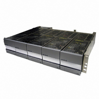
PWR SUP FNT END 48V 1000W 20A
Manufacturer
TDK Corporation
Series
TLr
Specifications of TL100048
Power Supply Type
Switching (Closed Frame)
Voltage - Output
48V
Number Of Outputs
1
Power (watts)
1000W
Applications
Commercial
Voltage - Input
90 ~ 264VAC
Mounting Type
Chassis Mount
1st Output
48 VDC @ 20A
Size / Dimension
11.12" L x 3.41" W x 3.45" H (282.4mm x 86.6mm x 87.6mm)
Power (watts) - Rated
1000W
Operating Temperature
-40°C ~ 65°C
Efficiency
92%
Approvals
CE, CSA, EN, UL
Line Regulation
±1%
Load Regulation
±1%
Power Supply Output Type
Fixed
No. Of Outputs
1
Output Voltage
48V
Output Current
20A
Power Rating
1000W
Input Voltage
90V AC To 264V AC
Length
282.448mm
Lead Free Status / RoHS Status
Lead free / RoHS Compliant
3rd Output
-
2nd Output
-
4th Output
-
Lead Free Status / RoHS Status
Lead free / RoHS Compliant, Lead free / RoHS Compliant
Other names
285-1646


3055 Del Sol Blvd • San Diego, CA 92154 • 1-800-LAMBDA-4
Pin Color
20
19
18
17
16
15
14
13
12
11
10
9
8
7
6
5
4
3
2
1
Alarm and Signal Interconnections
J1
Wire
BLK
RED
RED/WHT
RED/BLK
GRN/WHT
LT BL
LT BL/WHT
LT BL/BLK
YLW/WHT
YLW/BLK
TAN/WHT
TAN/BLK
TAN
GRN/BLK
GRN
OR/WHT
OR/BLK
OR
WHT
YLW
Description
Shelf Bias: A regulated 12V/100ma bias supply. Referenced to Pin 10.
SCL: I
SDA: I
Logic Ground: Isolated ground for opto-coupled alarms.
Module Disable: Opto-coupled input. Applying 5V between this pin
and Pin 17 will disable all modules in the shelf.
Module 0 (leftmost slot) AC Fail.
Module 1 AC Fail
Module 2 AC Fail
Module 3 AC Fail
Module 4 (rightmost slot) AC Fail
V Main Output (-). DC power ground.
I Shelf: Indicates average shelf current. Ratio varies with rectifier type.
Call factory for details.
V Margin: Applying a 0-5V signal from this pin to Pin 11 will linearly
change the output voltage by 0-10V.
Not Used
Module Thermal Limit Failure
Module 0 (leftmost slot) DC Fail.
Module 1 DC Fail
Module 2 DC Fail
Module 3 DC Fail
Module 4 (rightmost slot) DC Fail
2
2
C clock line. Referenced to Pin 10.
C data line. Referenced to Pin 10.
TLR5-S S ERIES POWER SYSTEM
Revision A3 : July 2005
Table 12
Page. 23
Related parts for TL100048
Image
Part Number
Description
Manufacturer
Datasheet
Request
R

Part Number:
Description:
TDK DC to DC Converters, DC to AC Inverters
Manufacturer:
TDK Corporation
Datasheet:
Part Number:
Description:
TDK DC to DC Converters, DC to AC Inverters
Manufacturer:
TDK Corporation
Datasheet: