ZUP120-1.8/U TDK Corporation, ZUP120-1.8/U Datasheet - Page 46
ZUP120-1.8/U
Manufacturer Part Number
ZUP120-1.8/U
Description
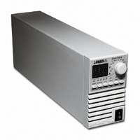
PWR SUP BENCH PROG 0-120V 216W
Manufacturer
TDK Corporation
Series
ZUPr
Type
Programmabler
Specifications of ZUP120-1.8/U
Load Regulation
0.01%
Voltage - Output
0 ~ 120V
Number Of Outputs
1
Power (watts)
216W
Applications
Commercial
Power Supply Type
Switching (Closed Frame)
Voltage - Input
85 ~ 265VAC
Mounting Type
Chassis Mount
1st Output
0 ~ 120 VDC @ 1.8A
Size / Dimension
13.78" L x 4.88" W x 2.76" H (350mm x 124mm x 70mm)
Power (watts) - Rated
216W
Operating Temperature
0°C ~ 50°C
Efficiency
82%
Approvals
CE, EN, UL
Line Regulation
0.01%
Power Supply Output Type
Variable
No. Of Outputs
1
Output Voltage
120V
Output Current
1.8A
Power Rating
216W
Input Voltage
85V AC To 265V AC
Length
350mm
Width
70mm
Accuracy
0.02% + 70 mV
Brand/series
ZUP
Current, Output
1.8 A
Display Type
Digital Meter
Power, Output
216 W
Power, Rating
216 W (Max.)
Regulation, Line
0.01% + 2 mA⁄1 mV + 0.005%
Regulation, Load
0.01% + 5 mA⁄2 mV + 0.005%
Standards
UL Listed, CE Marked
Temperature Coefficient
30 ppm⁄°C (CV)⁄100 ppm⁄°C (CC)
Temperature, Operating, Maximum
50 °C
Temperature, Operating, Minimum
0 °C
Voltage, Input
85-265 VAC
Voltage, Noise
80 mV @ 20 MHz BW
Voltage, Output
120 VDC
Voltage, Ripple
30 mV @ 5 Hz to 1 MHz
Lead Free Status / RoHS Status
Lead free / RoHS Compliant
3rd Output
-
2nd Output
-
4th Output
-
Lead Free Status / Rohs Status
RoHS Compliant part
Other names
285-1671
ZUP1201.8/U
ZUP1201.8/U


13
5
8
1
1
1
5.3.3 RS232 cable ( PC to ZUP ) - ZUP/NC403 , ZUP/NC401
The RS232 is used only for connecting the power supply to the controller PC. For linking several power
supplies, refer to par. 5.3.4.
Fig. 5-4: RS232 cable with DB-9
female connector -P/N: NC401.
5.3.4 Linking power supplies - ZUP/NC405 / ZUP/W
It is possible to link up to 31 ZUP units, using rear panel In/Out connectors and linking cables as shown
in Fig. 5-1. The first unit communicates with the PC via RS232 as shown in Figs. 5-3 and 5-4. The other
units are linked by RS485 interface. Construction of the linking cable is shown in Fig. 5-5.
Fig. 5-5: ZUP units linking cable.
P/N: ZUP/NC405
Fig. 5-3: RS232 cable with DB-25
female connector -P/N: NC403
ZUP/W
EIA/TIA-568A SHIELDED CONNECTORS
8 PIN CONNECTOR (IN) 8 PIN CONNECTOR (OUT) REMARKS
HOUSING
HOUSING
PIN NO.
DB-25 CONNECTOR
PIN NO.
PIN NO.
DB-9 CONNECTOR
1
2
3
7
2
3
5
5
2
4
6
8
SHIELD
TX
RX
SG
SHIELD
RX
TX
SG
SHIELD
SG
TXD
TXD
RXD
RXD
NAME
NAME
NAME
-
+
-
+
HOUSING
HOUSING
PIN NO.
PIN NO.
PIN NO.
3
7
5
8 PIN CONNECTOR
7
3
5
5
2
4
6
8
8 PIN CONNECTOR
NAME
SHIELD
RX
TX
SG
NAME
NAME
SHIELD
TX
RX
SG
SHIELD
SG
TXD
TXD
RXD
RXD
-
+
+
-
REMARKS
REMARKS
TWISTED
TWISTED
PAIR
PAIR
1
8
1
8
1
8
Related parts for ZUP120-1.8/U
Image
Part Number
Description
Manufacturer
Datasheet
Request
R

Part Number:
Description:
PWR SUP BENCH PROG 0-120V 432W
Manufacturer:
TDK Corporation
Datasheet:

Part Number:
Description:
ZERO UP PROGRAMMABLE POWER SUPPLIES
Manufacturer:
TDK Corporation
Part Number:
Description:
TDK DC to DC Converters, DC to AC Inverters
Manufacturer:
TDK Corporation
Datasheet:
Part Number:
Description:
TDK DC to DC Converters, DC to AC Inverters
Manufacturer:
TDK Corporation
Datasheet: