ZUP120-1.8/U TDK Corporation, ZUP120-1.8/U Datasheet - Page 47
ZUP120-1.8/U
Manufacturer Part Number
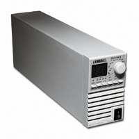
ZUP120-1.8/U
Description
PWR SUP BENCH PROG 0-120V 216W
Manufacturer
TDK Corporation
Series
ZUPr
Type
Programmabler
Specifications of ZUP120-1.8/U
Load Regulation
0.01%
Voltage - Output
0 ~ 120V
Number Of Outputs
1
Power (watts)
216W
Applications
Commercial
Power Supply Type
Switching (Closed Frame)
Voltage - Input
85 ~ 265VAC
Mounting Type
Chassis Mount
1st Output
0 ~ 120 VDC @ 1.8A
Size / Dimension
13.78" L x 4.88" W x 2.76" H (350mm x 124mm x 70mm)
Power (watts) - Rated
216W
Operating Temperature
0°C ~ 50°C
Efficiency
82%
Approvals
CE, EN, UL
Line Regulation
0.01%
Power Supply Output Type
Variable
No. Of Outputs
1
Output Voltage
120V
Output Current
1.8A
Power Rating
216W
Input Voltage
85V AC To 265V AC
Length
350mm
Width
70mm
Accuracy
0.02% + 70 mV
Brand/series
ZUP
Current, Output
1.8 A
Display Type
Digital Meter
Power, Output
216 W
Power, Rating
216 W (Max.)
Regulation, Line
0.01% + 2 mA⁄1 mV + 0.005%
Regulation, Load
0.01% + 5 mA⁄2 mV + 0.005%
Standards
UL Listed, CE Marked
Temperature Coefficient
30 ppm⁄°C (CV)⁄100 ppm⁄°C (CC)
Temperature, Operating, Maximum
50 °C
Temperature, Operating, Minimum
0 °C
Voltage, Input
85-265 VAC
Voltage, Noise
80 mV @ 20 MHz BW
Voltage, Output
120 VDC
Voltage, Ripple
30 mV @ 5 Hz to 1 MHz
Lead Free Status / RoHS Status
Lead free / RoHS Compliant
3rd Output
-
2nd Output
-
4th Output
-
Lead Free Status / Rohs Status
RoHS Compliant part
Other names
285-1671
ZUP1201.8/U
ZUP1201.8/U


5
1
Fig. 5-7: RS485 cable with
5.4
DB-9 female connector.
5.4.1 Introduction
For operation environments that require high noise immunity or long distance communication, it is
recommended to use the built-in RS485 interface. The RS485 interface is accessible through the
rear panel In/Out jacks in a similar way to the RS232. The communication is a four-wire type. Refer to
par. 5-6 for detailed explanation. Up to 31 ZUP units can be connected to the RS485 control as shown
in Fig. 5-6.
Fig. 5-6: Linking ZUP units to RS485 control.
5.4.2 RS485 cable ( PC to ZUP ) - NC402
5.4.3 Linking power supplies
Power supplies are linked in the same way as described in par. 5.3.4.
5.5
The ZUP command set is divided into four categories as follows: 1. Initialization Control
The commands structure, syntax, and registers definition are described in this paragraph as listed
above.
REMOTE PROGRAMMING VIA RS485
ZUP SERIES COMMAND SET DESCRIPTION
RS485
ZUP (1)
1000m max.
HOUSING
RS485
PIN NO.
DB-9 CONNECTOR
9
8
1
5
4
ZUP (2)
SHIELD
TXD
TXD
SG
RXD
RXD
NAME
-
+
-
+
2. ID Control
3. Output Control
4. Status Control
RS485
HOUSING
PIN NO.
6
8
5
2
4
8 PIN CONNECTOR
NAME
SHIELD
RXD
RXD
SG
TXD
TXD
ZUP (31)
+
+
-
-
REMARKS
TWISTED
TWISTED
PAIR
PAIR
1
8
Related parts for ZUP120-1.8/U
Image
Part Number
Description
Manufacturer
Datasheet
Request
R

Part Number:
Description:
PWR SUP BENCH PROG 0-120V 432W
Manufacturer:
TDK Corporation
Datasheet:

Part Number:
Description:
ZERO UP PROGRAMMABLE POWER SUPPLIES
Manufacturer:
TDK Corporation
Part Number:
Description:
TDK DC to DC Converters, DC to AC Inverters
Manufacturer:
TDK Corporation
Datasheet:
Part Number:
Description:
TDK DC to DC Converters, DC to AC Inverters
Manufacturer:
TDK Corporation
Datasheet: