SWT40-5FF TDK Corporation, SWT40-5FF Datasheet - Page 12
SWT40-5FF
Manufacturer Part Number
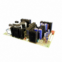
SWT40-5FF
Description
PWR SUP 40W +5 +15 -15V TRIPLE
Manufacturer
TDK Corporation
Series
SWT40r
Specifications of SWT40-5FF
Voltage - Output
5V, ±15V
Number Of Outputs
3
Power (watts)
40W
Applications
Commercial
Power Supply Type
Switching (Open Frame)
Voltage - Input
85 ~ 265VAC
Mounting Type
Chassis Mount
1st Output
5 VDC @ 3A
2nd Output
15 VDC @ 1.5A
3rd Output
-15 VDC @ 300mA
Size / Dimension
5" L x 3" W x 1.4" H (127mm x 76.2mm x 35.6mm)
Power (watts) - Rated
40W
Operating Temperature
0°C ~ 50°C
Efficiency
70%
Approvals
CSA, DENAN, EN, UL
Line Regulation
1%, 2%
Load Regulation
2%, 4%
4th Output
-
Other names
285-1073
SWT405FF
SWT405FF


Alpha II
ZWD-
Genesys
ZWS-
FPS
HK-A
HWS
MTW
RKE
RTW
UNA
ZWQ
DLP
JWS-P
RKY
SWT
VS-P
ZUP
ZWS
JWT
PAF
PAF
VS
A-284
SWT
Pay attention to all warnings and cautions before using the unit.
Incorrect usage could lead to an electric shock, damage to the
unit or a fire hazard.
● Do not touch the internal components, they may have high
● When the unit is operating, keep your hands and face away
● Input must be off when making connections.
● Output current of each connector must be less than 5A.
● Connect FG terminal of input connector and mountale
● Use the input/output connector housing, terminal pin as
SWT30, 40 Component Side
SWT65 Component Side
voltage or high temperature. You may get electric shock or
burned.
from it; an accident may injure you.
FG to ground terminal of the equipment.
specified in outline drawing.
SWT30, 40 Terminal Explanation
SWT65 Terminal Explanation
WARNING
SERIES
Input
Input
BEFORE USING THE POWER SUPPLY UNIT
Component Side
Component Side
SWT Series Instruction Manual
1. Terminal Explanation
Output
Output
● This power supply is primarily designed and manufactured to
● Never operate the unit under over current or shorted condi-
● This power supply is PC board type unit. Please hold the
● Connector housing and terminal pin are not included
● Also, use recommended crimping tool.
use and enclosed in other equipment.
tions for 30 seconds or more, which could result in damage
or insulation failure.
board edge while mounting, and do not touch the component
side.
with this product.
CAUTION
① FG(1) terminal (pin 1 of CN1)
FG(2) terminal (faston terminal)
Connect FG(1) or FG(2) to safety ground of ap-
② AC input terminal (pin 4 of CN1)
L: Live line (fuse in line)
③ AC input terminal (pin 6 of CN1)
N: Neutral line
④ Protective earth: Must be connected to electri-
⑤ CH2 +V output terminal (pin 1 of CN2)
⑥ CH1 +5V output terminal (pin 2 and 3 of CN2)
⑦ GND CH1, CH2, CH3 common ground terminal
⑧ CH3 -V output terminal (pin 6 of CN2)
① FG(1) terminal (pin 1 of CN1)
FG(2) terminal (faston terminal)
Connect FG(1) or FG(2) to safety ground of ap-
② AC input terminal (pin 4 of CN1)
L: Live line (fuse in line)
③ AC input terminal (pin 6 of CN1)
N: Neutral line
④ Protective earth: Must be connected to electri-
⑤ CH1 +5V output terminal (pin 1 and 2 of CN2)
⑥ GND CH1, CH2, CH3 common ground terminal
⑦ CH2 +V output terminal (pin 5 and 6 of CN2)
⑧ CH3 -V output terminal (pin 7 of CN2)
(pin4-5 of CN2)
(pin3-4 of CN2)
paratus or equipment.
cally safe ground of apparatus or equipment by
electrically conductive spacers.
paratus or equipment.
cally safe ground of apparatus or equipment by
electrically conductive spacers.
・All specifications are subject to change without notice.
Related parts for SWT40-5FF
Image
Part Number
Description
Manufacturer
Datasheet
Request
R

Part Number:
Description:
PWR SUP 40W +5 +12 -12V TRIPLE
Manufacturer:
TDK Corporation
Datasheet:
Part Number:
Description:
SWITCH MODE POWER SUPPLY
Manufacturer:
TDK Corporation
Datasheet:

Part Number:
Description:
TDK DC to DC Converters, DC to AC Inverters
Manufacturer:
TDK Corporation
Datasheet:
Part Number:
Description:
TDK DC to DC Converters, DC to AC Inverters
Manufacturer:
TDK Corporation
Datasheet: