PL-USB-BLASTER-RCN Altera, PL-USB-BLASTER-RCN Datasheet - Page 17
PL-USB-BLASTER-RCN
Manufacturer Part Number
PL-USB-BLASTER-RCN
Description
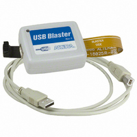
CABLE PROGRAMMING USB
Manufacturer
Altera
Series
USB-Blaster™r
Datasheet
1.PL-USB-BLASTER-RCN.pdf
(29 pages)
Specifications of PL-USB-BLASTER-RCN
Accessory Type
Download Cable
Core Architecture
FPGA
Core Sub-architecture
Arria, Cyclone, Stratix
Ic Product Type
Debugger / Programmer
Kit Contents
Device, Cable, Guides
Rohs Compliant
Yes
For Use With/related Products
EPCS Serial Configuration Devices
Lead Free Status / RoHS Status
Lead free / RoHS Compliant
Other names
544-1775
PL-USB-BLTER-RCN-OB
PL-USB-BLTER-RCN-OB
Available stocks
Company
Part Number
Manufacturer
Quantity
Price
Company:

Part Number:
PL-USB-BLASTER-RCN
Manufacturer:
ALTERA
Quantity:
1


Overview
USB-Blaster Connections
Voltage Requirements
© April 2009 Altera Corporation
This chapter provides comprehensive information about the USB-Blaster
cable including the following:
■
■
■
■
The USB-Blaster cable has a USB universal plug that connects to the PC USB port, and
a 10-pin female plug that connects to the circuit board. Data is downloaded from the
USB port on the PC through the USB-Blaster cable to the circuit board via the
connections discussed in this section.
The USB-Blaster VCC(TRGT) pin must be connected to a specific voltage for the
device being programmed. Connect pull-up resistors to the same power supply as the
USB-Blaster V
Table 2–1. USB-Blaster VCC(TRGT) Pin Voltage Requirements (Part 1 of 2)
MAX
MAX 7000S device
MAX 7000AE and
MAX 3000A devices
MAX 7000B devices
Arria II GX devices
Stratix III and
Stratix IV devices
Cyclone
Stratix II, Stratix,
Stratix II GX, Stratix
GX, and Arria GX
devices
“USB-Blaster Connections” on page 2–1
■
■
■
■
“Operating Conditions” on page 2–5
“USB-Revision” on page 2–7
“Statement of China-RoHS Compliance” on page 2–8
Device Family
®
“Voltage Requirements” on page 2–1
“Cable-to-Board Connection” on page 2–2
“USB-Blaster Plug Connection” on page 2–3
“Circuit Board Header Connection” on page 2–4
II devices
®
III devices
CC(TRGT).
As specified by V
5 V
3.3 V
2.5 V
As specified by V
As specified by V
As specified by V
As specified by V
See
Table
2–1.
CCIO
CCPD or
CCPGM
CCA
CCSEL
2. USB-Blaster Specifications
USB-Blaster VCC Voltage Required
or V
of Bank 1
or V
V
CCIO
CCIO
CCPD
of Bank 8C
USB-Blaster Download Cable User Guide
™
download
Related parts for PL-USB-BLASTER-RCN
Image
Part Number
Description
Manufacturer
Datasheet
Request
R

Part Number:
Description:
CYCLONE II STARTER KIT EP2C20N
Manufacturer:
Altera
Datasheet:


Part Number:
Description:
CPLD, EP610 Family, ECMOS Process, 300 Gates, 16 Macro Cells, 16 Reg., 16 User I/Os, 5V Supply, 35 Speed Grade, 24DIP
Manufacturer:
Altera Corporation
Datasheet:
Part Number:
Description:
CPLD, EP610 Family, ECMOS Process, 300 Gates, 16 Macro Cells, 16 Reg., 16 User I/Os, 5V Supply, 15 Speed Grade, 24DIP
Manufacturer:
Altera Corporation
Datasheet:
Part Number:
Description:
Manufacturer:
Altera Corporation
Datasheet:
Part Number:
Description:
CPLD, EP610 Family, ECMOS Process, 300 Gates, 16 Macro Cells, 16 Reg., 16 User I/Os, 5V Supply, 30 Speed Grade, 24DIP
Manufacturer:
Altera Corporation
Datasheet:
Part Number:
Description:
High-performance, low-power erasable programmable logic devices with 8 macrocells, 10ns
Manufacturer:
Altera Corporation
Datasheet:
Part Number:
Description:
High-performance, low-power erasable programmable logic devices with 8 macrocells, 7ns
Manufacturer:
Altera Corporation
Datasheet:
Part Number:
Description:
Classic EPLD
Manufacturer:
Altera Corporation
Datasheet:
Part Number:
Description:
High-performance, low-power erasable programmable logic devices with 8 macrocells, 10ns
Manufacturer:
Altera Corporation
Datasheet:
Part Number:
Description:
Manufacturer:
Altera Corporation
Datasheet:
Part Number:
Description:
Manufacturer:
Altera Corporation
Datasheet:
Part Number:
Description:
Manufacturer:
Altera Corporation
Datasheet:
Part Number:
Description:
CPLD, EP610 Family, ECMOS Process, 300 Gates, 16 Macro Cells, 16 Reg., 16 User I/Os, 5V Supply, 25 Speed Grade, 24DIP
Manufacturer:
Altera Corporation
Datasheet: