ATSTK524 Atmel, ATSTK524 Datasheet - Page 10
ATSTK524
Manufacturer Part Number
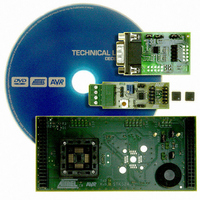
ATSTK524
Description
KIT STARTER ATMEGA32M1/MEGA32C1
Manufacturer
Atmel
Datasheet
1.ATSTK524.pdf
(20 pages)
Specifications of ATSTK524
Accessory Type
Daughter Board
For Use With/related Products
STK500
For Use With
ATSTK500 - PROGRAMMER AVR STARTER KIT
Lead Free Status / RoHS Status
Lead free / RoHS Compliant


10
AVR078
Figure 4-3.
The ISP connector is used for the ATmega32M1/C1 built-in debugWire interface. The pin out of
the connector is shown in
from Atmel. Connecting a JTAGICE mkII to this connector allows On-chip Debugging of the
ATmega32M1/C1.
More information about the JTAGICE mkII and On-chip Debugging can be found in the AVR
JTAGICE mkII User Guide, which is available at the Atmel web site, www.atmel.com.
Note:
Table 4-2.
Squid Cable
Colours
green
black
grey
Remove the RESET jumper on the STK500 to work run properly JTAGICE mkII.
Connecting JTAGICE mkII to the STK524
STK524 ISP/DW Connector Pinout
Target pins
RESET
MISO
SCK
Table 4-2
and is compliant with the pin out of the JTAG ICE available
STK524 ISP pinout
1
3
5
2
4
6
Target pins
MOSI
GND
VTG
Squid Cable
7780A–AVR–02/08
Colours
purple
brown
red
Related parts for ATSTK524
Image
Part Number
Description
Manufacturer
Datasheet
Request
R

Part Number:
Description:
DEV KIT FOR AVR/AVR32
Manufacturer:
Atmel
Datasheet:

Part Number:
Description:
INTERVAL AND WIPE/WASH WIPER CONTROL IC WITH DELAY
Manufacturer:
ATMEL Corporation
Datasheet:
Part Number:
Description:
Low-Voltage Voice-Switched IC for Hands-Free Operation
Manufacturer:
ATMEL Corporation
Datasheet:
Part Number:
Description:
MONOLITHIC INTEGRATED FEATUREPHONE CIRCUIT
Manufacturer:
ATMEL Corporation
Datasheet:
Part Number:
Description:
AM-FM Receiver IC U4255BM-M
Manufacturer:
ATMEL Corporation
Datasheet:
Part Number:
Description:
Monolithic Integrated Feature Phone Circuit
Manufacturer:
ATMEL Corporation
Datasheet:
Part Number:
Description:
Multistandard Video-IF and Quasi Parallel Sound Processing
Manufacturer:
ATMEL Corporation
Datasheet:
Part Number:
Description:
High-performance EE PLD
Manufacturer:
ATMEL Corporation
Datasheet:
Part Number:
Description:
8-bit Flash Microcontroller
Manufacturer:
ATMEL Corporation
Datasheet:
Part Number:
Description:
2-Wire Serial EEPROM
Manufacturer:
ATMEL Corporation
Datasheet: