ATSTK524 Atmel, ATSTK524 Datasheet - Page 11
ATSTK524
Manufacturer Part Number
ATSTK524
Description
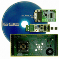
KIT STARTER ATMEGA32M1/MEGA32C1
Manufacturer
Atmel
Datasheet
1.ATSTK524.pdf
(20 pages)
Specifications of ATSTK524
Accessory Type
Daughter Board
For Use With/related Products
STK500
For Use With
ATSTK500 - PROGRAMMER AVR STARTER KIT
Lead Free Status / RoHS Status
Lead free / RoHS Compliant


4.4
4.5
7780A–AVR–02/08
STK524 Jumpers, Leds & Test Points
UART connection
Note:
Table 4-3.
(1)
on page 4
Table 4-4.
The STK524 includes a Rx/Tx 2-pin header which enables to connect the ATmega32M1/C1
UART Tx/Rx lines to Tx/Rx lines of STK500 as shown on
Figure 4-4.
Jumper
JP1
JP2
JP3
JP4
JP5
JP6
Test Point
T1
T2
: Let it opened if the address resistor of the AVRLINAdapt is selected.See
MISO, MOSI & SCK lines can be disconnected when the product is in debugging mode. These
can be used then for application purpose.
STK524 Jumpers
STK524 Test Points
UART connection
Function
VTG
ANA REF
ISRC
POT_SUPPLY
POT
TxD RxD
Function
GND
AREF
Description
Useful to measure the VCC and AVCC current
Connect STK500 REF circuit to AVR AREF
Closed to have a 1K resistor on ISRC pin
Always closed, enable to supply potentiometer
JP5.2 is output of potentiometer to connect either on signal
port on STK500 or ADC input.
UART lines to connect to TxD & RxD line on STK500, see
Figure 4.5
Description
Electrical ground of the STK524 board
AREF pin of the AVR
UART connection
Figure
4-3.
(1)
“LIN bus adapter.”
AVR078
11
Related parts for ATSTK524
Image
Part Number
Description
Manufacturer
Datasheet
Request
R

Part Number:
Description:
DEV KIT FOR AVR/AVR32
Manufacturer:
Atmel
Datasheet:

Part Number:
Description:
INTERVAL AND WIPE/WASH WIPER CONTROL IC WITH DELAY
Manufacturer:
ATMEL Corporation
Datasheet:
Part Number:
Description:
Low-Voltage Voice-Switched IC for Hands-Free Operation
Manufacturer:
ATMEL Corporation
Datasheet:
Part Number:
Description:
MONOLITHIC INTEGRATED FEATUREPHONE CIRCUIT
Manufacturer:
ATMEL Corporation
Datasheet:
Part Number:
Description:
AM-FM Receiver IC U4255BM-M
Manufacturer:
ATMEL Corporation
Datasheet:
Part Number:
Description:
Monolithic Integrated Feature Phone Circuit
Manufacturer:
ATMEL Corporation
Datasheet:
Part Number:
Description:
Multistandard Video-IF and Quasi Parallel Sound Processing
Manufacturer:
ATMEL Corporation
Datasheet:
Part Number:
Description:
High-performance EE PLD
Manufacturer:
ATMEL Corporation
Datasheet:
Part Number:
Description:
8-bit Flash Microcontroller
Manufacturer:
ATMEL Corporation
Datasheet:
Part Number:
Description:
2-Wire Serial EEPROM
Manufacturer:
ATMEL Corporation
Datasheet: