CY3280-BBM Cypress Semiconductor Corp, CY3280-BBM Datasheet - Page 4
CY3280-BBM
Manufacturer Part Number
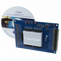
CY3280-BBM
Description
MODULE BREADBOARD CAPSENSE
Manufacturer
Cypress Semiconductor Corp
Series
CapSense™r
Datasheet
1.CY3280-BBM.pdf
(8 pages)
Specifications of CY3280-BBM
Mfg Application Notes
Capacitance Sensing - AppNote CapSense Best Practices - AppNote
Design Resources
CY3280-BBM Schematic
Accessory Type
Prototyping Board
Interface Type
Serial
Operating Voltage
5 V
Silicon Manufacturer
Cypress
Silicon Core Number
CAP1073264
Kit Application Type
Sensing - Touch / Proximity
Application Sub Type
Capacitive Touch
Rohs Compliant
No
Lead Free Status / RoHS Status
Lead free / RoHS Compliant
For Use With/related Products
CY3280 Module Board
For Use With
428-2987 - CAPSENSE CONTROLLER DEV KIT
Lead Free Status / Rohs Status
Lead free / RoHS Compliant
Other names
428-2992


Page: 4
4. Review CapSense Best Practices
The Universal CapSense Controller was created using the best practices for
CapSense layout. To enable universality and development of the kit and its projects,
certain design elements have been changed from what is recommended for final prod-
ucts. Below is a list of the design features in the Universal CapSense Controller and
what to change for final products.
Sensing traces
routed through
a connector to
sensors.
Sensing traces
routed to other
schematic
elements.
Sensing traces
located on the
top layer.
Several
regulators
used, including
a variable
regulator.
Test point on
CMOD.
Feature
Design
Buttons, sliders, and
LEDs are placed on the
module board to allow for
greater flexibility with
custom modules for
development and
subsequent releases.
Universality of the board
enabled by population/
depopulation of 0-Ω
resistors.
Using vias to route
traces to bottom of board
and back to connector
increases parasitic
capacitance.
Demonstration of
CapSense at several
voltages.
Accessibility of charge/
discharge waveforms.
Reason
Connectors increase the
parasitic capacitance of
the sensors, effectively
reducing their sensitivity.
Connectors also create
another path for noise to
enter the system.
Solder pads of 0-Ω
resistors increase
parasitic capacitance.
Possible noise sensitivity
to stimulus on top side of
board. Finger presses on
routing of control board
can lead to sensor
activation.
Global and User Module
parameters may need to
be verified with changing
power supply.
A test point increases
noise sensitivity by
acting as an antenna.
Impact
Sensors and control
circuitry should be
located on the same
printed circuit board.
Lower parasitic
capacitance by reducing
trace lengths.
Route traces directly to
sensing elements. Use
as few 0-Ω resistors as
possible.
Route sensing traces on
non-user side of printed
circuit board. Route
sensing traces as far
from noise sources as
possible.
Supply one regulated
voltage to PSoC.
Solder pad test points
for leads offer better
noise immunity if test
points are required.
Recommended
Change
Related parts for CY3280-BBM
Image
Part Number
Description
Manufacturer
Datasheet
Request
R

Part Number:
Description:
KIT UNIVERSAL CAPSENSE CTRLR
Manufacturer:
Cypress Semiconductor Corp
Datasheet:

Part Number:
Description:
BOARD EVAL CAPSENSE EXPRESS
Manufacturer:
Cypress Semiconductor Corp
Datasheet:

Part Number:
Description:
CAPSENSE CONTROLLER DEV KIT
Manufacturer:
Cypress Semiconductor Corp
Datasheet:

Part Number:
Description:
MODULE LINEAR SLIDER CAPSENSE
Manufacturer:
Cypress Semiconductor Corp
Datasheet:

Part Number:
Description:
MODULE RADIAL SLIDER CAPSENSE
Manufacturer:
Cypress Semiconductor Corp
Datasheet:

Part Number:
Description:
MODULE SIMPLE BUTTON CAPSENSE
Manufacturer:
Cypress Semiconductor Corp
Datasheet:

Part Number:
Description:
MODULE MATRIXED BUTTON CAPSENSE
Manufacturer:
Cypress Semiconductor Corp
Datasheet:

Part Number:
Description:
BOARD DEV CAPSENSE CTLR
Manufacturer:
Cypress Semiconductor Corp
Part Number:
Description:
BOARD DEV CAPSENSE CTLR
Manufacturer:
Cypress Semiconductor Corp
Part Number:
Description:
KIT DEV CAPSENSE CTLR UNIV
Manufacturer:
Cypress Semiconductor Corp
Datasheet:

Part Number:
Description:
MODULE CAPSENSE PLUS
Manufacturer:
Cypress Semiconductor Corp
Datasheet:
Part Number:
Description:
SmartSense Evaluation Kit
Manufacturer:
Cypress Semiconductor Corp
Part Number:
Description:
Manufacturer:
Cypress Semiconductor Corp
Datasheet: