AC1059 Analog Devices Inc, AC1059 Datasheet - Page 2
AC1059
Manufacturer Part Number
AC1059
Description
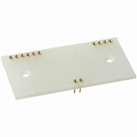
SOCKET FOR MODEL AD210 IC
Manufacturer
Analog Devices Inc
Specifications of AC1059
Accessory Type
Mating Socket
Connector Type
DIP Socket
No. Of Contacts
12
Pitch Spacing
2.54mm
Row Pitch
20.32mm
Contact Termination
Through Hole
Socket Mounting
PC Board
Number Of Contacts
12
Primary Type
AD210
Lead Free Status / RoHS Status
Lead free / RoHS Compliant
For Use With/related Products
AD210
Lead Free Status / RoHS Status
Contains lead / RoHS non-compliant, Lead free / RoHS Compliant


Model
GAIN
INPUT VOLTAGE RATINGS
INPUT IMPEDANCE
INPUT BIAS CURRENT
INPUT DIFFERENCE CURRENT
INPUT NOISE
FREQUENCY RESPONSE
OFFSET VOLTAGE (RTI)
RATED OUTPUT
ISOLATED POWER OUTPUTS
POWER SUPPLY
TEMPERATURE RANGE
PACKAGE DIMENSIONS
NOTES
*Specifications same as AD210AN.
1
2
3
4
Specifications subject to change without notice.
AD210–SPECIFICATIONS
Nonlinearity is specified as a % deviation from a best straight line..
RTI – Referred to Input.
A reduced signal swing is recommended when both V
See text for detailed information.
loaded, due to supply voltage reduction.
Range
Error
vs. Temperature(0 C to +70 C)
vs. Supply Voltage
Nonlinearity
Linear Differential Range
Maximum Safe Differential Input
Max. CMV Input-to-Output
Common-Mode Rejection
R
Leakage Current Input-to-Output
Differential
Common Mode
Initial, @ +25 C
vs. Temperature (0 C to +70 C)
Initial, @ +25 C
vs. Temperature(0 C to + 70 C)
Voltage (l kHz)
Current (1 kHz)
Bandwidth (–3 dB)
Settling Time ( 10 mV, 20 V Step) *
Slew Rate (G = 1 V/V)
Initial, @ +25 C
vs. Temperature (0 C to +70 C)
Voltage, 2 k Load
Impedance
Ripple (Bandwidth = 100 kHz)
Voltage, No Load
Accuracy
Current
Regulation, No Load to Full Load
Ripple
Voltage, Rated Performance
Voltage, Operating
Current, Quiescent
Current, Full Load – Full Signal
Rated Performance
Operating
Storage
Inches
Millimeters
S
ac, 60 Hz, Continuous
dc, Continuous
60 Hz, G = 100 V/V
@ 240 V rms, 60 Hz
G = 1 V/V
G = 100 V/V
G = 1 V/V
G = 100 V/V
500
(10 Hz to 10 kHz)
Impedance Imbalance
1
(–25 C to +85 C)
(–25 C to +85 C)
(–25 C to +85 C)
(–25 C to +85 C) 30 nA max
3
2
4
AD210AN
1 V/V – 100 V/V
+25 ppm/ C max
*
2500 V rms
*
*
120 dB
*
2 A rms max
l0
5 G
30 pA typ (400 pA max) *
10 nA max
5 pA typ (200 pA max) *
2 nA max
10 nA max
18 nV/ Hz
4 V rms
0.01 pA/ Hz
*
20 kHz
15 kHz
150 s
500 s
1 V/ s
( 10 30/G) V/ C
( 10 50/G) V/ C
1
10 mV p-p max
See Text
See Text
+15 V dc
+15 V dc
50 mA
80 mA
–25 C to +85 C
–40 C to +85 C
–40 C to +85 C
1.00
25.4
2% max
50 ppm/ C max
0.002%/V
0.025% max
10 V
15 V
3500 V peak
15 45/G) mV max
10 V min
15 V
10%
5 mA
12
max
5 pF
2.10
53.3
5%
10%
0.350
8.9
ISS
and V
AD210BN
*
*
*
*
*
*
*
*
*
*
*
*
*
*
*
*
*
*
*
*
*
*
*
( 5 15/G) mV max
*
*
*
*
*
*
*
*
*
*
*
*
*
*
*
*
*
*
*
*
OSS
(typical @ +25 C, and V
1% max
0.012% max
supplies are fully
_
–2–
AD210JN
*
*
*
*
*
*
*
*
1500 V rms
*
*
*
*
*
*
*
*
*
*
*
*
*
*
*
*
*
*
*
*
*
*
*
*
*
*
*
*
*
*
*
*
*
*
*
*
*
*
2000 V peak
S
= +15 V unless otherwise noted)
Pin
1
2
3
4
14
15
16
17
18
19
29
30
CAUTION
ESD (electrostatic discharge) sensitive device. Elec-
trostatic charges as high as 4000 V readily accumu-
late on the human body and test equipment and can
discharge without detection. Although the AD210
features proprietary ESD protection circuitry, per-
manent damage may occur on devices subjected to
high energy electrostatic discharges. Therefore,
proper ESD precautions are recommended to avoid
performance degradation or loss of functionality.
Designation
O
+V
–V
+V
–V
FB
–IN
I
+IN
Pwr Com
Pwr
V
COM
COM
O
OSS
ISS
Dimensions shown in inches and (mm).
OSS
ISS
AD210 PIN DESIGNATIONS
OUTLINE DIMENSIONS
WARNING!
AC1059 MATING SOCKET
ESD SENSITIVE DEVICE
Function
Output
Output Common
+Isolated Power @ Output
–Isolated Power @ Output
+Isolated Power @ Input
–Isolated Power @ Input
Input Feedback
–Input
Input Common
+Input
Power Common
Power Input
REV. A
Related parts for AC1059
Image
Part Number
Description
Manufacturer
Datasheet
Request
R

Part Number:
Description:
±1.7g Dual-Axis IMEMS Accelerometer Evaluation Board
Manufacturer:
Analog Devices Inc
Datasheet:

Part Number:
Description:
Inertial Sensor Evaluation System
Manufacturer:
Analog Devices Inc
Datasheet:
Part Number:
Description:
Manufacturer:
Analog Devices Inc
Datasheet:
Part Number:
Description:
Manufacturer:
Analog Devices Inc
Datasheet:
Part Number:
Description:
Manufacturer:
Analog Devices Inc
Datasheet:
Part Number:
Description:
Manufacturer:
Analog Devices Inc
Datasheet:
Part Number:
Description:
Manufacturer:
Analog Devices Inc
Datasheet:
Part Number:
Description:
Manufacturer:
Analog Devices Inc
Datasheet:
Part Number:
Description:
Manufacturer:
Analog Devices Inc
Datasheet:
Part Number:
Description:
Manufacturer:
Analog Devices Inc
Datasheet:
Part Number:
Description:
Manufacturer:
Analog Devices Inc
Datasheet:
Part Number:
Description:
Manufacturer:
Analog Devices Inc
Datasheet:
Part Number:
Description:
Manufacturer:
Analog Devices Inc
Datasheet: