DC9S08QE8 Freescale Semiconductor, DC9S08QE8 Datasheet
DC9S08QE8
Specifications of DC9S08QE8


Related parts for DC9S08QE8

DC9S08QE8 Summary of contents
Page 1
...
Page 2
Purchase Agreement P&E Microcomputer Systems, Inc. reserves the right to make changes without further notice to any products herein to improve reliability, function, or design. P&E Microcomputer Systems, Inc. does not assume any liability arising out of the application or ...
Page 3
INTRODUCTION ............................................................................................ 1 1.1 Overview ........................................................................................................ 1 1.2 Package Contents .......................................................................................... 1 1.3 Supported Devices ......................................................................................... 1 1.4 Recommended Materials On DEMO9S08QB8 Resources CD...................... 1 1.5 Handling Precautions ..................................................................................... 2 2 HARDWARE FEATURES............................................................................... 2 2.1 DEMOQE Base Board Features ...
Page 4
Quick Start Application .................................................................................21 6.2 Serial Accelerometer Application ..................................................................22 7 JUMPER SETTINGS .................................................................................... 22 7.1 System Power...............................................................................................22 7.2 RS232 Communications ...............................................................................24 7.3 LED Display Port ..........................................................................................26 7.4 Input and Reset Switches .............................................................................27 7.5 3-Axis Accelerometer Jumper Settings.........................................................28 7.6 Buzzer...........................................................................................................30 ...
Page 5
INTRODUCTION 1.1 Overview The DEMO9S08QB8 is a low-cost development system designed for demonstrating, evaluating, and debugging the Freescale MC9S08QB8 microcontroller. P&E’s Embedded Multilink circuitry on the DEMO9S08QB8 board allows the processor on the DEMO9S08QB8 to be debugged and programmed ...
Page 6
DEMO9S08QB8 User Manual (this document) • DEMO9S08QB8 Quick Start Guide • DEMO9S08QB8 Quick Start Application Source Code • DEMO9S08QB8 Base Board and Daughter Cards Schematics • DEMO9S08QB8 Component Breakdown List • DEMOQE Toolkit Applications • Links to P&E Evaluation ...
Page 7
P&E’s Embedded Multilink circuitry populated on the bottom • RS-232 Serial Port w/ DB9-F Connector • SCI signals connected to P&E’s Embedded Multilink through jumpers • ON/OFF Power Switch w/ LED indicator • A 5VDC to 8VDC power supply ...
Page 8
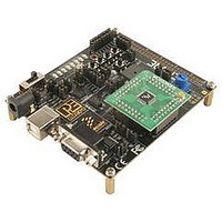
Specifications: • • Note: The DEMOQE board power connector is incorrectly labelled as 5-12VDC. The maximum voltage is 8VDC. Figure 2-1: DEMOQE Top Component Placement 2.2 On-Board Logic Analyzer The DEMOQE board has a built-in 2-channel logic analyzer which ...
Page 9
On-Board Virtual Serial Port The DEMOQE board has a built-in virtual serial port which may be connected to the QE processor’s SCI RXD/TXD. This allows certain PC applications to be able to connect in a serial fashion to the ...
Page 10
SIGNALS OF QB8 PTB4-5 PTB6/XTAL PTB7/EXTAL PTC0-5 PTC6 PTC7 2.6 Signal Mapping of DC9S08QB8 to MCU_PORT MCU PORT NUMBER SIGNALS OF DEMOQE BOARD PTB4-5 PTB6/XTAL PTB7/EXTAL PTC0-5 PTE6/LED PTE7/LED Signal Mapping MC9S08QB8 ...
Page 11
MCU PORT NUMBER DEMO9S08QB8 User Manual Signal Mapping MC9S08QB8 PIN PORT SIGNAL NUMBER PTC1 NC PTB4 NC PTB5/TPMCH0 NC PTA6 NC ...
Page 12
MCU PORT NUMBER SYSTEM SETUP 3.1 Overview P&E’s Embedded Multilink driver is required to operate the DEMO9S08QB8 using a PC. The Embedded Multilink driver should be installed with the CodeWarrior Development Studio software or from the DEMOQE ...
Page 13
Note: After installation of CodeWarrior 6. also required that you install the S08QB8 service pack. 3.3.2 Installing P&E Resources Use the DEMOQE Resources DVD-ROM to access and install P&E resources for the DEMO9S08QB8. These materials are not required ...
Page 14
Step 6. Figure 3-1: DEMOQE Logic Analyzer Application 3.5 Hardware Setup 3.5.1 First-Time Connection The DEMO9S08QB8 may be connected through a USB port. Connection steps are listed below in typical order: 1. Install the required software, as ...
Page 15
Plug the USB cable B-M connector into the USB connector on the DEMOQE Base Board. 5. The operating system will recognize P&E’s Embedded Multilink cir- cuitry and P&E’s USB to Serial circuitry. Depending on the operating system, you may ...
Page 16
Figure 3-3: Found New Hardware Wizard Dialog ( Click the “Finish” button to exit the current “Found New Hardware Wizard”. 7. Depending on the operating system, you may see the “Found New Hardware Wizard” dialog again, helping you ...
Page 17
Figure 3-4: Found New Hardware Wizard Dialog ( Select the “Install the software automatically (Recommended)” option and click the “Next” button. 8. Windows will install the driver files to your system. At the end of the installation, the ...
Page 18
Figure 3-5: Found New Hardware Wizard Dialog ( Click the “Finish” button to exit the “Found New Hardware Wizard”. If the DEMO9S08QB8 hardware interface driver is now properly installed on your system, the green USB LED on the ...
Page 19
Section 8 - DEMO9S08QB8 CODE DEVELOPMENT SOFTWARE for more information. 4.3 Run Mode The DEMO9S08QB8’s rich component list empowers it to perform a variety of tasks. Once an application is developed, debugged, and programmed properly into the QB8 internal flash ...
Page 20
This PC-based application is used to display the logic analyzer data on the PC. The logic analyzer data is displayed in real-time and each waveform may be paused, zoomed, and printed. If the microcontroller-based Quick Start Application is programmed into ...
Page 21
DEMOQE Terminal Application This PC-based application acts as a standard serial port terminal application on the PC. It works with standard serial ports as well as the virtual serial port on the DEMOQE board. The application includes settings to ...
Page 22
Figure 5-3: DEMOQE Unsecure Application This PC-based application is included on the DVD-ROM that accompanies the DEMOQE, and may also be found at: http://www.pemicro.com/fixedlinks/demoQEtoolkit.html. 5.4 DEMOQE Accelerometer Demo Application This PC-based application will graph serial data output from the microcontroller-based ...
Page 23
Figure 5-4: Accelererometer Demo Application The data that is graphed may come from either the PC serial port or the virtual serial port on the DEMOQE board. The serial port of the microcontroller on the DEMOQE board is routed to ...
Page 24
All data to be displayed must be in hexadecimal format. The data can be accepted and displayed either as incoming byte values ($00-$FF) or word values ($0000-$FFFF). The data format indicates whether the data is byte or word data. The ...
Page 25
As can be seen in Section 5.5.2 - Data Format, each incoming data command affecting the graphing component must have new data for all four waveforms. An ...
Page 26
5.5.2.2 Word Formatted Data There are three commands which may be accepted. All commands must end in the special characters #$0D and #$0A which are CR (carriage return) and LF (line feed). ...
Page 27
The source code for this Quick Start Application is also included on the DVD- ROM. The DEMOQE toolkit may also be found at: http://www.pemicro.com/fixedlinks/demoQEtoolkit.html. 6.2 Serial Accelerometer Application ...
Page 28
Figure 7-1 shows the regulator input selection details. Select regulator input from DC power jack. A 5-8VDC center positive power supply must be used. Note: The DEMOQE board power connector is ...
Page 29
J5 - VDD Source Selection Jumper VDD_SELECT Select the regulator to supply microcontroller VDD. This is the default setting. Select the battery pack to supply microcontroller VDD Select the MCU_PORT to supply microcontroller VDD. This setting also allows power ...
Page 30
J6 - SCI RXD Signal Selection Jumper RXD_EN Connects the microcontroller PTB0/RXD signal to the RS232 transceiver. Connects the microcontroller PTB0/RXD signal to the Embedded Multilink SCI circuitry. This is the default setting. Figure 7-4: SCI RXD Signal Selection ...
Page 31
J8 - SCI Transceiver Enable COM_EN (J8) Enables the SCI Transceiver. The user may control PTC5 in firmware to enable or disable the transceiver. Disables the SCI Transceiver. This is the default setting. Figure 7-6: SCI Transceiver Enable/Disable Selection ...
Page 32
Figure 7-7: LED Display Enable Header LED_ENABLE (J9) Note: LED PTE6 and LED PTE7 are mapped to QB8 ports PTC6 and PTC7 respectively. 7.4 Input and Reset Switches The DEMO9S08QB8 has an option to connect two signals, PTC0 and PTC1, ...
Page 33
J12 - Light Touch Switch Enable Jumper KEY_ENABLE Enables the corresponding switch. Each jumper may be individually installed or removed. By default, all jumpers are installed to enable all the switches. Figure 7-9: Jumper Settings for Light Touch Switches ...
Page 34
TABLE 1. G-SEL2 1 1 7.5.1 J13 - Accelerometer g-Select1 Jumper G-SEL1 Selects g-Select1 to be logic low. This is the default setting. Selects g-Select1 to be logic high. A user may control PTD0 in firmware to set g-Select1. Figure ...
Page 35
Figure 7-12: Accelerometer g-Select2 Jumper settings (J14) 7.5.3 J15 - Accelerometer Sleep Mode Select Jumper SLEEP (J15) Enables the 3-axis accelerometer. This is the default setting. Puts the 3-axis accelerometer into sleep mode. The user may control PTC4 in firmware ...
Page 36
J19 - Buzzer enable jumper BUZ_EN Enables Buzzer to be controlled by PTB5. This is the default setting. Figure 7-15: Accelerometer Signal Output ACC_EN (J19) 7.7 IIC Pull-up The MC9S08QB8 does not have a dedicated IIC module. Installing IIC_EN ...
Page 37
J17 - External Crystal Circuitry Enable Jumpers CLOCK_EN Enables or disables the external crystal circuitry. Both positions must be installed to enable use of crystal circuitry. Figure 7-18: External Crystal Circuitry Enable Jumper CLOCK_EN (J17) 7.10 Optional Jumpers For ...
Page 38
Using P&E Software With The DEMO9S08QB8 P&E offers software tools for Freescale’s HCS08 devices that can be used to develop code for the DEMO9S08QB8 board. P&E offers an integrated development environment, which combines a command-line assembler, in- circuit debugger, ...
Page 39
Below is an overview of the features and intended use of the USB Multilink and Cyclone PRO. 9.1.1 USB Multilink Key Features • Direct user control of target’s execution • Programming and debugging capabilities • Read/write registers and memory values ...
Page 40
Figure 9-1: P&E’s USB Multilink (USB-ML-12 shown) 9.2.1 Product Features & Implementation P&E’s USB Multilink Interface (USB-ML-12) connects your target to your PC and allows the PC access to the Background Debug Mode (BDM) on Freescale’s ColdFireV1, HCS08, RS08, and ...
Page 41
Product Features & Implementation P&E’s Cyclone PRO is an extremely flexible tool designed for debugging, testing, and in-circuit flash programming of Freescale’s ColdFireV1, HC08, HCS08, RS08, and HC(S)12(X) microcontrollers. The Cyclone PRO connects your target to the PC via ...
Page 42
DEMO9S08QB8 hardware. If this dialog indicates that the DEMO9S08QB8 hardware is not connected to the PC, the first step is to make sure that the DEMO9S08QB8 hardware is connected to the PC via a USB 2.0 high-speed cable ...
Page 43
Resources DVD-ROM to make sure all files were properly installed. This may give some indication of what the problem is. (D) Using a USB Hub The DEMO9S08QB8 is a high-power USB device USB Hub is used, it must ...
Page 44
Select the Hardware tab. 2. Click on the Device Manager button. 3. Select the "System Devices" in the Device Manager window. 4. Expand the tree index (+) for System Devices the bottom of the System Devices list, ...
Page 45
...