AC164335 Microchip Technology, AC164335 Datasheet - Page 125
AC164335
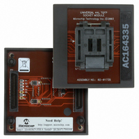
Manufacturer Part Number
AC164335
Description
MODULE SKT FOR 10X10 PM3 44TQFP
Manufacturer
Microchip Technology
Datasheet
1.AC164335.pdf
(286 pages)
Specifications of AC164335
Module/board Type
Socket Module - TQFP
Product
Microcontroller Accessories
Lead Free Status / RoHS Status
Not applicable / Not applicable
For Use With/related Products
MPLAB® PM3
For Use With
DV007003 - PROGRAMMER UNIVERSAL PROMATE II
Lead Free Status / RoHS Status
Lead free / RoHS Compliant, Not applicable / Not applicable


12.4.7
Constant Off-Time mode is shown in Figure 12-9.
Constant Off-Time PWM is a variable-frequency mode
where the actual PWM period is less than or equal to
the specified period value. The PWM time base is
externally reset some time after the PWM signal duty
cycle value has been reached, and the PWM signal has
been deasserted. This mode is implemented by
enabling the On-Time PWM mode (Current Reset
mode) and using the complementary output.
FIGURE 12-9:
12.4.8
Current Reset PWM is shown in Figure 12-10. Current
Reset PWM uses a Variable-Frequency mode where
the actual PWM period is less than or equal to the spec-
ified period value. The PWM time base is externally
reset some time after the PWM signal duty cycle value
has been reached and the PWM signal has been deas-
serted. Current Reset PWM is a constant on-time PWM
mode.
FIGURE 12-10:
© 2006 Microchip Technology Inc.
Period
Value
Period
Value
PWML
PWMH
0
0
Note: Duty Cycle represents off time
External Timer Reset
External Timer Reset
Timer
Value
Actual Period
Duty Cycle
Timer
Value
Programmed Period
Duty Cycle
CONSTANT OFF-TIME PWM
CURRENT RESET PWM MODE
Actual Period
Programmed Period
Programmed Period
CONSTANT OFF-TIME
PWM
CURRENT RESET PWM
Duty Cycle
Duty Cycle
External Timer Reset
External Timer Reset
Preliminary
Typically, in the converter application, an energy stor-
age inductor is charged with current while the PWM
signal is asserted, and the inductor current is dis-
charged by the load when the PWM signal is deas-
serted. In this application of current reset PWM, an
external current measurement circuit determines when
the inductor is discharged, and then generates a signal
that the PWM module uses to reset the time base
counter. In Current Reset mode, complementary
outputs are available.
12.4.9
Independent
Figure 12-11, is often used when the dsPIC DSC is
controlling different power converter subcircuits such
as the Power Factor Correction circuit, which may use
100 kHz PWM, and the full-bridge forward converter
section may use 250 kHz PWM.
FIGURE 12-11:
PWM1H
PWM2H
PWM3H
PWM4H
dsPIC30F1010/202X
Note:
INDEPENDENT TIME BASE PWM
Duty Cycle
Duty Cycle
Duty Cycle
Time
Period 1
With independent time bases,
PWM signals are no longer
phase related to each other.
Duty Cycle
Base
INDEPENDENT TIME
BASE PWM
Period 2
Period 3
PWM,
Period 4
DS70178C-page 123
as
shown
in
Related parts for AC164335
Image
Part Number
Description
Manufacturer
Datasheet
Request
R

Part Number:
Description:
Manufacturer:
Microchip Technology Inc.
Datasheet:
Part Number:
Description:
Manufacturer:
Microchip Technology Inc.
Datasheet:
Part Number:
Description:
Manufacturer:
Microchip Technology Inc.
Datasheet:
Part Number:
Description:
Manufacturer:
Microchip Technology Inc.
Datasheet:
Part Number:
Description:
Manufacturer:
Microchip Technology Inc.
Datasheet:
Part Number:
Description:
Manufacturer:
Microchip Technology Inc.
Datasheet:
Part Number:
Description:
Manufacturer:
Microchip Technology Inc.
Datasheet:
Part Number:
Description:
Manufacturer:
Microchip Technology Inc.
Datasheet: