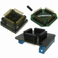
Z8F64220100ZDA Zilog, Z8F64220100ZDA Datasheet - Page 2

Z8F64220100ZDA
Manufacturer Part Number
Z8F64220100ZDA
Description
ADAPTER ICE Z8 ENCORE 64K 64LQFP
Manufacturer
Zilog
Specifications of Z8F64220100ZDA
Module/board Type
*
For Use With/related Products
Z8 Encore!™
Lead Free Status / RoHS Status
Contains lead / RoHS non-compliant
Other names
269-3403
Z8 Encore! XP
The errata listed in
codes prior to 0344, where the date code is YYWW (year and week of assembly). When reviewing the fol-
lowing errata, it is recommended that you also download the most recent version of the Product Specifica-
tion.
Table 2. Z8 Encore! XP F64XX Series Errata Date Coded Prior to 0334
UP006010-0508
Sl
No. Summary
1
2
3
When the CPU exits
from HALT mode, it
fails to reset the
master Interrupt
Request Enable
(IRQE) bit.
System reset
latency may exceed
specification limits.
UART NEWFRM sta-
tus bit does not func-
tion.
Table 2
®
F64XX Series with Date Codes Prior to 0344
are found in the production Z8 Encore! XP
Description
When the CPU exits from HALT mode, it fails to reset the master Interrupt
Request Enable (IRQE) bit (bit 7 of the Interrupt Control Register).
WDT interrupts cause the program counter (PC) and Flags to be pushed twice
on the stack. The first push is the PC and Flags from where the interrupt
occurred. The second push is the starting address and Flags of the Interrupt
service routine (ISR).
This problem also affects exits from HALT mode caused by other interrupt
sources if more than one interrupt is pending. If only a single interrupt is pend-
ing then, the routine is executed normally except that interrupts are not dis-
abled
Workaround
To mimic standard interrupt operation, the ISR should execute a disable inter-
rupts (DI) instruction to reset the master Interrupt Request enable (IRQE) bit to
0.
Further, on WDT interrupts before exiting, the ISR should add three to the
stack pointer (SP). On normal interrupts, the ISR should check the program
counter on the stack. If the PC on the stack contains the starting address of
the ISR, then the ISR should add three to the stack pointer. This problem only
affects exits from HALT mode.
When exiting STOP mode and after a Power-On Reset (POR)/Voltage Brown-
out (VBO) reset, the system reset Latency is 514 WDT cycles plus 16 system
clock cycles rather than the 66 WDT cycles plus 16 system clock cycles as
specified.
Workaround
None. This error is unlikely to affect system operation.
The NEWFRM status bit (bit 2 of the UART Status 1 register) does not indicate
the start of a new frame.
Workaround
None
Errata for Z8 Encore! XP
®
F64XX Series devices with date
®
F64XX Series
Page 2 of 5


