PBMCUSLK Freescale Semiconductor, PBMCUSLK Datasheet - Page 9
PBMCUSLK
Manufacturer Part Number
PBMCUSLK
Description
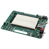
PROJECT BOARD FOR MCU
Manufacturer
Freescale Semiconductor
Datasheet
1.PBMCUSLK.pdf
(30 pages)
Specifications of PBMCUSLK
Module/board Type
Student Learning Kit
Silicon Manufacturer
Freescale
Core Architecture
HCS08, S12
Core Sub-architecture
HCS08, S12
Silicon Core Number
MC9S08, MC9S12
Silicon Family Name
S08QG, S12D
Rohs Compliant
Yes
For Use With/related Products
HC(S)12(X), HC(S)08, DSP, and ColdFire modules
Lead Free Status / RoHS Status
Lead free / RoHS Compliant


When attached to the NI-ELVIS workstation, the 5V rail is driven through connector J1 from the
workstation. Refer to the NI-ELVIS workstation user manual for further details.
The 3.3V rail is supplied from an on-board regulator located at VR2.
connected to the 5V input through selection header PSEL_B. VR2 supplies a maximum of
500mA of current to the project board. The 3.3V regulator also features over-current and over-
temperature protection.
The ±15V rails are supplied from either an on-board boost regulator at PS1 or the NI-ELVIS
workstation through connector J1. The PS1 input is derived from VIN connector through the
regulator at VR1. If powered from VIN and an external power supply, current on the ±15V rails
is limited to 50 mA. In this configuration, PS1 will consume 500mA of current output from VR1.
If powered from the NI-ELVIS workstation, the ± 15V rails are provided directly from the
workstation. The workstation will provide a maximum current on the ±15V rails of 500 mA.
The PS1 voltages and the J1 voltages are diode OR’ed to prevent component damage.
Total current available is dependent on the configuration chosen and the load placed on each
voltage rail. For instance, consider the following setup. The project board is powered from a
transformer connected to VIN. A 50mA load is placed on the +15V and the –15V rails for the
analog portion of the circuit. Additionally, a 500mA load is placed on the 3.3V rail. In this
configuration, any load placed on the 5V rail will cause an over-current condition in regulator
VR1.
Table 1 below lists current limits for each voltage rail in different input configurations. Each
current limit shows the maximum provided except in the case of the USB input. The USB input
assumes the USB circuitry consumes 200mA of peak current. It is the users responsibility to
ensure current limits are not exceeded in any configuration.
Table 1: Current Limits
Freescale Semiconductor
NOTE: 3.3V rail is derived from 5V rail for all inputs. Total current available on 3.3V rail
5V, 300mA
3.3V, 200mA
N/A
5V, 500mA
3.3V, 500mA
±15V, 50mA
5V, 500mA
3.3V, 500mA
±15V, 500mA
±12V, 500mA
is limited by total current available on 5V rail.
Total current drain from USB bus must not exceed 500 mA. Excessive
current drain will violate the USB specification.
The VR2 input is
9
Related parts for PBMCUSLK
Image
Part Number
Description
Manufacturer
Datasheet
Request
R

Part Number:
Description:
Manufacturer:
Freescale Semiconductor, Inc
Datasheet:
Part Number:
Description:
Manufacturer:
Freescale Semiconductor, Inc
Datasheet:
Part Number:
Description:
Manufacturer:
Freescale Semiconductor, Inc
Datasheet:
Part Number:
Description:
Manufacturer:
Freescale Semiconductor, Inc
Datasheet:
Part Number:
Description:
Manufacturer:
Freescale Semiconductor, Inc
Datasheet:
Part Number:
Description:
Manufacturer:
Freescale Semiconductor, Inc
Datasheet:
Part Number:
Description:
Manufacturer:
Freescale Semiconductor, Inc
Datasheet:
Part Number:
Description:
Manufacturer:
Freescale Semiconductor, Inc
Datasheet:
Part Number:
Description:
Manufacturer:
Freescale Semiconductor, Inc
Datasheet:
Part Number:
Description:
Manufacturer:
Freescale Semiconductor, Inc
Datasheet:
Part Number:
Description:
Manufacturer:
Freescale Semiconductor, Inc
Datasheet:
Part Number:
Description:
Manufacturer:
Freescale Semiconductor, Inc
Datasheet:
Part Number:
Description:
Manufacturer:
Freescale Semiconductor, Inc
Datasheet:
Part Number:
Description:
Manufacturer:
Freescale Semiconductor, Inc
Datasheet:
Part Number:
Description:
Manufacturer:
Freescale Semiconductor, Inc
Datasheet: