AT90USBKEY2 Atmel, AT90USBKEY2 Datasheet
AT90USBKEY2
Specifications of AT90USBKEY2
AT90USBKEY


Related parts for AT90USBKEY2


AT90USBKEY2 Summary of contents
Page 1
AT90USBKey ............................................................................................. Hardware User Guide ...
Page 2
AT90USBKey Hardware User Guide User Guide Section 1 Introduction ........................................................................................... 1-3 1.1 Overview ...................................................................................................1-3 1.2 AT90USBKey Features............................................................................1-4 Section 2 Using the AT90USBKey ....................................................................... 2-5 2.1 Overview ...................................................................................................2-5 2.2 Power Supply ............................................................................................2-6 2.3 Reset.........................................................................................................2-8 2.4 On-board Resources.................................................................................2-9 2.5 In-System Programming .........................................................................2-13 ...
Page 3
Overview AT90USBKey Hardware User Guide Congratulations on acquiring the AVR® AT90USBKey. This kit is designed to give designers a quick start to develop code on the AVR® and for prototyping and testing of new designs with the AT90USB microcontroller ...
Page 4
... The most recent version of AVR Studio®, AVR tools and this User Guide can be found in the AVR section of the Atmel web site, http://www.atmel.com. 2. ATMEL Flip®, In System Programming Version 3 or Higher shall be used for Device Firmware Upgrade. Please consult Atmel web site to retrieve the latex version of Flip and the DFU bootloader Hex file if needed ...
Page 5
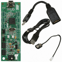
Overview AT90USBKey Hardware User Guide Using the AT90USBKey This chapter describes the AVRUSBKey and all its resources. Figure 2-1 . AT90USBKey Overview Section 2 2-5 7627A–AVR–04/06 ...
Page 6
Using the AT90USBKey 2.2 Power Supply 2.2.1 Power Supply Sources USB powered When used as a USB device bus powered application, the AVRUSBKey can be directly Battery powered The external battery connector should be used when the AT90USBKey is used ...
Page 7
VBUS Generator 2.2.3 “POWER-ON“ LED AT90USBKey Hardware User Guide When using the AT90USB microcontroller in USB host mode, the AT90USBKey should provide a 5V power supply over the VBUS pin of its USB mini AB connector. A couple of ...
Page 8
Using the AT90USBKey 2.3 Reset 2.3.1 Power-on RESET 2.3.2 RESET Push Button 2.3.3 Main Clock XTAL 2-8 7627A–AVR–04/06 Although the AT90USB has its on-chip RESET circuitry (c.f. AT90USB Datasheet, section “System Control and Reset), the AVRUSBKey provides to the AT90USB ...
Page 9
On-board Resources 2.4.1 USB 2.4.2 Joystick AT90USBKey Hardware User Guide The AVRUSBKey is supplied with a standard USB mini A-B receptacle. The mini AB receptacle allows to connect both a mini A plug or a mini B plug connectors. ...
Page 10
Using the AT90USBKey 2.4.3 LEDs 2.4.4 Temperature Sensor 2-10 7627A–AVR–04/06 The AT90USBKey includes 2 bi-color LEDs (green/red) implemented on one line. They are connected to the high nibble of “Port D” of AT90USB (PORTD[4..7]). To light on a LED, the ...
Page 11
AT90USBKey Hardware User Guide The NTC thermistor used in AT90USBKey has a resistance of 100 KΩ and a beta-value of 4250 ±3%. By the use of the following equation, the temperature (T) can be calculated: β ...
Page 12
Using the AT90USBKey 2.4.5 Data Flash memory PB[7..0] VCC3 R9 100k PE0 PB1 PB2 PB3 RESET 2-12 7627A–AVR–04/06 Temp. R Temp. T (°C) (KΩ) (°C) 5 278,995 35 6 264,119 36 7 250,134 37 8 236,981 38 9 224,606 39 ...
Page 13
... AT90USB. This is the easiest and fastest way to reprogram the device directly over the USB interface. The “Flip” PC side application, is available from the Atmel website, offers a flexible an user friendly interface to reprogram the application over the USB bus. ...
Page 14
... Thus the on-chip flash bootloader will be erased. It can be restored after the debug session using the bootloader hex file available from ATMEL website. AT90USBKey Hardware User Guide ...
Page 15
AT90USBKey Hardware User Guide Figure 3-1 . Troubleshooting Guide Problem The Green “VCC-ON” LED is not on No power supply AVRUSBKey does not work The AVR JTAG ICE probe is not connected The memory lock bits are programmed The AT90USB ...
Page 16
AT90USBKey Hardware User Guide Technical Specifications System Unit – Physical Dimensions .....................................................L=90 x W=30 x H=8 mm – Weight ...........................................................................................................12 g Operating Conditions – Internal Voltage Supply ............................................................................... 3.3V – External Voltage Supply .........................................................................8V -15V Connections – USB Connector ......................................................................Mini ...
Page 17
... AT90USBKey Hardware User Guide For Technical support, please contact avr@atmel.com. When requesting technical support, please include the following information: Which target AVR device is used (complete part number) Target voltage and speed Clock source and fuse setting of the AVR Programming method (ISP, JTAG or specific Boot-Loader) Hardware revisions of the AVR tools, found on the PCB Version number of AVR Studio ...
Page 18
AT90USBKey Hardware User Guide On the next pages, the following documents of AT90USBKey are shown: Complete schematics, Bill of materials. Section 6 Complete Schematics 6-18 7627A–AVR–04/06 ...
Page 19
PE7 PE5 PE3 PE1 PE0 PE2 PE4 PE6 PF7 PF5 PF3 PF1 PF0 PF2 PF4 PF6 AT90USBKey Hardware User Guide Figure 6-1 . Schematics PD7 PD5 PD3 PC3 PD1 PC1 PD0 PC0 PD2 PC2 PD4 PD6 PA2 ...
Page 20
Complete Schematics 6-20 7627A–AVR–04/06 Figure 6-2 . Schematics PF3 PF0 AT90USBKey Hardware User Guide ...
Page 21
Item Q.ty Reference 1 2 CR1,CR2 2 10 C1,C2,C3,C4,C5,C6,C12, C13, C18, C20 C8,C9, C17 5 2 C10, C11 6 3 C14, C16, C19 7 1 C15 8 2 D2, D3,D4 ...
Page 22
... Disclaimer: The information in this document is provided in connection with Atmel products. No license, express or implied, by estoppel or otherwise,to anyintellectu- alproperty right is granted by this document or in connection with the sale of Atmel products. EXCEPT AS SET FORTH IN ATMEL’S TERMS AND CONDI-TIONS OF SALE LOCATED ON ATMEL’S WEB SITE, ATMEL ASSUMES NO LIABILITY WHATSOEVER AND DISCLAIMS ANY EXPRESS, IMPLIED OR STATUTORYWAR- RANTY RELATING TO ITS PRODUCTS INCLUDING, BUT NOT LIMITED TO, THE IMPLIED WARRANTY OF MERCHANTABILITY, FITNESS FOR A PARTICU- LARPURPOSE, OR NON-INFRINGEMENT ...