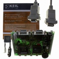
AT89STK-06 Atmel, AT89STK-06 Datasheet
AT89STK-06
Specifications of AT89STK-06


Related parts for AT89STK-06


AT89STK-06 Summary of contents
Page 1
... AT89STK-06 Demo Board .............................................................................................. Hardware User Guide ...
Page 2
... AT89STK-06 Demo Board User Guide Section 1 Introduction ........................................................................................... 1-1 1.1 Features ....................................................................................................1-1 Section 2 Hardware Description ........................................................................... 2-3 2.1 Block Diagram...........................................................................................2-3 2.2 Power Supply ............................................................................................2-3 2.3 RESET ......................................................................................................2-4 2.4 Serial Interfaces ........................................................................................2-5 2.5 Board Settings ..........................................................................................2-7 Section 3 Device Programming .......................................................................... 3-11 3.1 In-System Programming .........................................................................3-11 Section 4 Appendix A: Board Layout ...
Page 3
... Features AT89STK-06 Demo Board Software Demonstration Guide This document describes the board included in the AT89STK-06 Starter Kit dedicated to the T89C51CC01/CC02 and AT89C51CC03 CAN microcontrollers (for T89C51CC02 optionnal adaptor is required). This board is designed to allow an easy evaluation of the product using demonstration software. ...
Page 4
... Introduction Figure 1-1. AT89STK-06 board 1-2 4339C–CAN–07/05 AT89STK-06 Demo Board Software Demo Guide ...
Page 5
... INT0, INT1 t°C 2.2 Power Supply 2.2.1 Power Supply Sources J4 - JACK PWR connector: AT89STK-06 Demo Board Software Demonstration Guide Figure 2-1 shows a functional block diagram of the AT89STK-06 board, with the I/O usage. CAN Applicable MCU Generic Sensor LED Board Connector Generic Board (optionnal) Human The on-board power supply circuitry allows various power supply configurations ...
Page 6
... Although the AT89C51CC03 & AT89C51AC3 microcontrollers have on-chip RESET circuitry (c.f. microcontroller datasheet), the AT89STK-06 board provides to the microcontroller a RESET signal witch can come from 2 different sources: The on-board RC network acts as power-on RESET. By pressing the RESET push button on the AT89STK-06 board, a warm RESET of the microcontroller is performed ...
Page 7
... All CAN microcontrollers have one on-chip UART peripheral. Only the asynchronous mode is supported by the AT89STK-06 board. The AT89STK-06 board is supplied with a RS-232 driver/receiver. Only one female DB9 connector assumes the RS-232 connections. A full range of configuration can be set with two Rx lines and two Tx lines. ...
Page 8
... CAN 2.4.3 SPI 2-6 4339C–CAN–07/05 The microcontroller is a microcontroller with an on-chip full-CAN controller. The AT89STK-06 board is supplied with an Atmel CAN transceiver (ATA6660). A female DB9 connector assumes the CAN bus connections. Figure 2-7 . CAN DB9 Connections CAN DB9 front view 1 2 ...
Page 9
... JP4 RTS JP5 DTR JP6 Batt AT89STK-06 Demo Board Software Demo Guide The AT89STK-06 board has two types of settings: Jumpers Solder strap Test points Table 2-1, Table 2-2 and Table 2-3 provide an overview of the available settings and test points. Comments (guidelines) ...
Page 10
... Figure 2-11. Solder Strap definition “Open” Solder Pad When using T89C51CC02 or T89C5115 products with the AT89STK-06 board ( see ¨PLCC adapter for T89C51CC02 user guide: CANADAPT28), the SP1 solder pad should be closed to ensure correct hardware conditions setting on P1.0 port. SP1 solder pad connects ISP push button to P1.0 microcontroller port and the CANADAPT28 adapter should be inseted in U2 (PLCC44) socket ...
Page 11
... Test Points AT89STK-06 Demo Board Software Demonstration Guide Test points are used to check the internal power supply for AT89STK-06 Board. Table 2-3. Table of Test Points Reference PCB Name TP1 Vref Vref for ADC TP2 Vpot Test point for Potentiometer voltage ...
Page 12
... Auto ISP Mode 3.1.2.1 Board Configuration AT89STK-06 Demo Board Software Demonstration Guide The on-chip memories and configuration bytes of the AT89C51CC0x parts can be pro- grammed using the ISP mode of the device. To use ISP mode, the board should be configured as follow: POWER switch (SW1) on “ON” position EA jumper should be open (internal code execution only) ...
Page 13
... Device Programming 3-12 4339C–CAN–07/05 AT89STK-06 Demo Board Software Demo Guide ...
Page 14
... Figure 4-1. Board Components View Diagram J1 AT89STK-06 Demo Board Software Demonstration Guide Appendix A: Board Layout J2 Section 4 4-13 Rev. 4339C–CAN–07/05 ...
Page 15
... SW2, SW3, SW4, SW5 5 TP1, TP2, TP3, TP4, TP5, TP6 C3, C7, C9, C10, C12, C14, C15, C16, C17, C18, C19, C20, C21, C22, C23, C24, C25, C26, C27, 22 C29, C32 1 C11 1 C31 2 C5 C1, C2, C4 C28, C30 D1, D4 D2, D3, D6, D8 AT89STK-06 Demo Board Software Demo Guide ...
Page 16
... Figure 4-3. AT89STK-06 Board Schematics ( P1. 1 P1. 2 P1 AT89STK-06 Demo Board Software Demo Guide Appendix C: Board Schematics XTAL2 P4 XTAL1 A10 2/ P2 A11 3/ P2 TESTI A12 4/ P2 VSS A13 5/ P2 ESET VAG A14 6/ P2 VAR A15 T2EX P1. C TxD 0/ P4 ...
Page 17
... Appendix C: Board Schematics Figure 4-4. AT89STK-06 Board Schematics ( 4-16 4339C–CAN–07/05 AT89STK-06 Demo Board Software Demo Guide ...
Page 18
... Figure 4-5. AT89STK-06 Board Schematics ( AT89STK-06 Demo Board Software Demo Guide Appendix C: Board Schematics 4339C–CAN–07/05 4-17 ...
Page 19
... Appendix C: Board Schematics Figure 4-6. AT89STK-06 Board Schematics ( 4-18 4339C–CAN–07/ Bat t - Bat AT89STK-06 Demo Board Software Demo Guide ...
Page 20
... CANRes JP4 RTS JP5 DTR JP6 Batt AT89STK-06 Demo Board Software Demo Guide Appendix D: Default Configuration Function For T89C51CC02/T89C5115 usage, allow to redirect the ISP signal to P1.0, for hardware conditions. Connect PLCC44 Xtal2 to XTAL2 of the generic extension board Connect PLCC52 Xtal2 to XTAL2 of the generic extension ...
Page 21
... Appendix E: References/Acronyms AT89C51CC03, T89C51CC02, T89C51CC01, T89C5115, AT89C51AC3, T89C51AC2 Product Datasheets* API: Application Programming Interface FLIP: FLexible In-system Programming HPC: High Pin Count microcontroller (by opposition to LPC) ISP: In-System Programming LPC: Low Pin Count microcontroller AT89STK-06 Demo Board Software Demo Guide ...
Page 22
... Disclaimer: The information in this document is provided in connection with Atmel products. No license, express or implied, by estoppel or otherwise, to any intellectual property right is granted by this document or in connection with the sale of Atmel products. EXCEPT AS SET FORTH IN ATMEL’S TERMS AND CONDI- TIONS OF SALE LOCATED ON ATMEL’S WEB SITE, ATMEL ASSUMES NO LIABILITY WHATSOEVER AND DISCLAIMS ANY EXPRESS, IMPLIED OR STATUTORY WARRANTY RELATING TO ITS PRODUCTS INCLUDING, BUT NOT LIMITED TO, THE IMPLIED WARRANTY OF MERCHANTABILITY, FITNESS FOR A PARTICULAR PURPOSE, OR NON-INFRINGEMENT ...