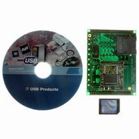
AT89STK-10 Atmel, AT89STK-10 Datasheet

AT89STK-10
Specifications of AT89STK-10
Related parts for AT89STK-10
AT89STK-10 Summary of contents
Page 1
... AT89STK-10 Starter Kit .............................................................................................. Hardware User Guide ...
Page 2
... AT89STK-10 Starter Kit Hardware User User Guide Section 1 Introduction ........................................................................................... 1-2 1.1 Features ....................................................................................................1-2 Section 2 Hardware Description ......................................................................... 2-10 Typical Applications ............................................................................ 2-11 3.1 Nand Flash Application ...........................................................................2-12 3.2 Serial Dataflash Application ....................................................................2-13 Section 3 Annex.................................................................................................. 3-14 4.1 Flash Evaluation Board ...........................................................................3-15 4.2 Nand Flash Add-on board .......................................................................3-18 1 7534A– ...
Page 3
... Features AT89STK-10 Starter Kit Hardware User Guide This document describes the Flash Evaluation Board dedicated to the AT89C5130/31A and the AT8xC5122D USB microcontrollers. This board is designed to enable an easy evaluation of the Mass Storage USB class using demonstration firmware (refer to firm- ware Guide). It must be plugged to a CPU board (AT89C5130/31A or AT8xC5122 D evaluation board) ...
Page 4
... AT89STK-10 Starter Kit Hardware User Guide Figure 1-1. Flash Evaluation Board Figure 1-2. Flash Evaluation Board with the related memories 1-2 Rev. 7534A–USB–07/05 ...
Page 5
... CPU board selection AT89STK-10 Starter Kit Hardware User Guide As mentioned above, the Flash evaluation board can be used either with the AT89C5130/31A or AT8xC5122 D. The figure below show the jumpers state to enable each mode : Figure 2-1. AT8xC5130/31AD Jumpers state Figure 2-2. Jumpers state ...
Page 6
... AT89STK-10 Starter Kit Hardware User Guide Figure 2-3. Flash evaluation board plugged to AT89C5130/31A evaluation board (AT89STK05) Warning : Before plugging the Flash Evoluation Board (AT89STK10) to the AT89C5130/31A evaluation board (AT89STK05), disconnect the three LEDs by remov- ing the solder on solder straps. The figure below shows the location of these solder straps : Figure 2-4 ...
Page 7
... Power supply AT89STK-10 Starter Kit Hardware User Guide Figure 2-5. Flash evaluation board plugged to AT8xC5122D evaluation board (AT89STK03) The Flash Evaluation Board power is supplied by the CPU board. The power supply must be set to 3.3V for the AT89C5131A Evaluation board and 3.6V for the AT8xC5122D Evaluation board. ...
Page 8
... Figure 2-9. Solder Straps location SP9 SP10 The tables hereunder show the configuration related to each memory mode : “Close” Solder location SP13 SP8 SP11 SP7 SP6 SP5 SP4 SP3 SP2 SP1 SP15 AT89STK-10 Starter Kit Hardware User Guide SP14 SP12 ...
Page 9
... AT89STK-10 Starter Kit Hardware User Guide Table 1. Nand Flash Configuration (Default configuration) Reference Name SP1..8 D0..7 SP9 CS SP10 R/ SER SP12 PAR SP 13 VccP SP 14 GNDP SP 15 CS_ext Table 2. On Board DataFlash Configuration (Serial mode) Reference Name Function SP1..8 D0..7 Connect bus P0 on onboard dataflash ...
Page 10
... SP12 PAR put DataFlash in parallel mode connect power supply of parallel SP 13 VccP interface of DataFlash connect gnd of parallel interface GNDP DataFlash SP 15 CS_ext Connect CS of external dataflash State Open Open Open Open Open Open Open Close AT89STK-10 Starter Kit Hardware User Guide ...
Page 11
... AT89STK-10 Starter Kit Hardware User Guide Typical Applications Section 3 Typical Applications 3-9 7534A–USB–07/05 ...
Page 12
... P2.0 P3.3 P2.1 Xtal1 P3.7 P2.3 Xtal2 P3.6 Ucap P3.0 AVss Vss 10µF Tantal. I/O.0 I/O.1 I/O.2 I/O.3 I/O.4 I/O.5 I/O.6 I/O.7 Vcc Vcc 10k Nand Flash 2. R/B CLE ALE Write Protection 2.2k AT89STK-10 Starter Kit Hardware User Guide Vcc Vss ...
Page 13
... Application 3.3V regulator 1.5k Vbus D+ D- GND USB connector 10nF 100 optional Vcc 2.2k 100k ISP 22pF 22pF 1µF AT89STK-10 Starter Kit Hardware User Guide Vcc 100nF 10µF Tantal. VDD AVDD P0.0 Vref P0 P0.4 P0.5 PLLF 2.2nF P0.6 P0.7 ...
Page 14
... Annex 4-12 7534A–USB–07/05 Section 4 Annex AT89STK-10 Starter Kit Hardware User Guide ...
Page 15
... SER/nPAR CLK 1 SI HE13 _4 FD HE13 HE13 _13 FD HE13 _13 FD AT89STK-10 Starter Kit Hardware User Guide NF_nWP2 nWP NF_nWP0 nWP Vcc Vcc NF_CLE CLE NF_ALE ALE NF_R/nB1 R/nB1 NF_nCE0 nCE0 NF_R/nB0 R/nB0 NF_nCE1 nCE1 NF_nRE nRE NF_nWE nWE J4 J4 NF_nWP3 1 nWP ...
Page 16
... R/nB0 P2_5 21 nCE1 P2_6 19 P2_6 P2_7 17 P2_7 P4_0 15 MISO_H P4_1 13 MOSI_H P4_2 11 CLK_H 9 7 TP10 TP10 HEADER 24X2 HEADER 24X2 flashbord Right flashbord Right Flash Board Right AT89STK-10 Starter Kit Hardware User Guide 48 46 Vss 44 Vss Vss 24 Vss Vss 4 Vss Vss ...
Page 17
... AT89STK-10 Starter Kit Hardware User Guide Annex 4-15 7534A–USB–07/05 ...
Page 18
... Annex 4.2 Nand Flash Add- on board 4-16 7534A–USB–07/05 Figure 4-1. Schematic AT89STK-10 Starter Kit Hardware User Guide ...
Page 19
... AT89STK-10 Starter Kit Hardware User Guide Figure 4-2. Component Side Figure 4-3. Solder Side Annex 4-17 7534A–USB–07/05 ...
Page 20
... Atmel does not make any commitment to update the information contained herein. Unless specifically providedot- herwise, Atmel products are not suitable for, and shall not be used in, automotive applications. Atmel’sAtmel’s products are not intended, authorized, or warranted for use as components in applications intended to support or sustain life. © ...


